Note
The SB-400 transmitter was released about six months after the SB-300 receiver; it was designed as a matching unit and represents the second product in the SB series.
The SB-400 was first seen in October 1963 issues of QST, CQ and 73 magazine. An ad for the SB-300 receiver in those publications included small teaser images of the SB-100, SB-200 and SB-400 with the text “Watch for these new Heathkit releases.” The SB-400 did not actually appear for sale in the catalog for another seven months.
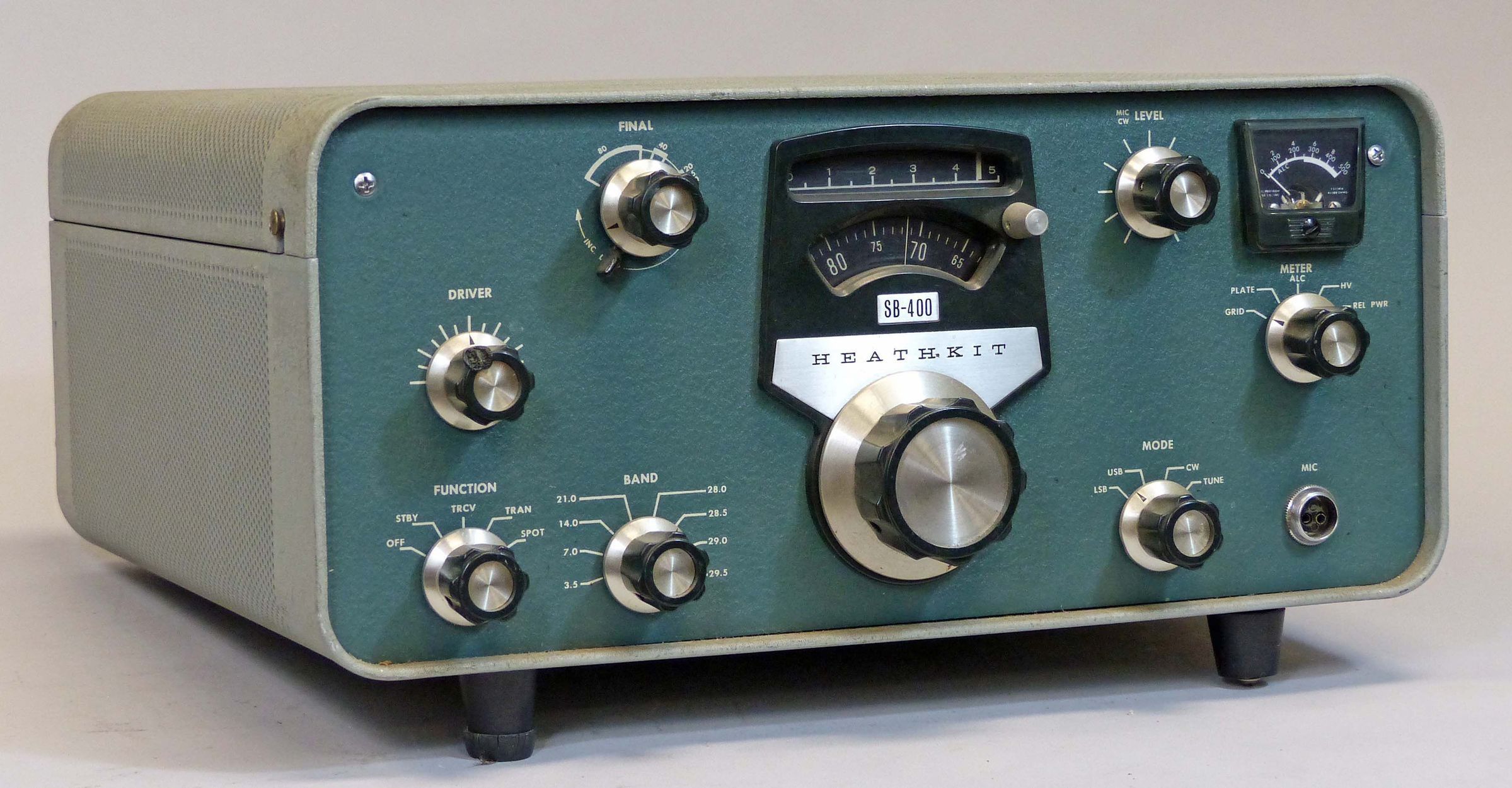
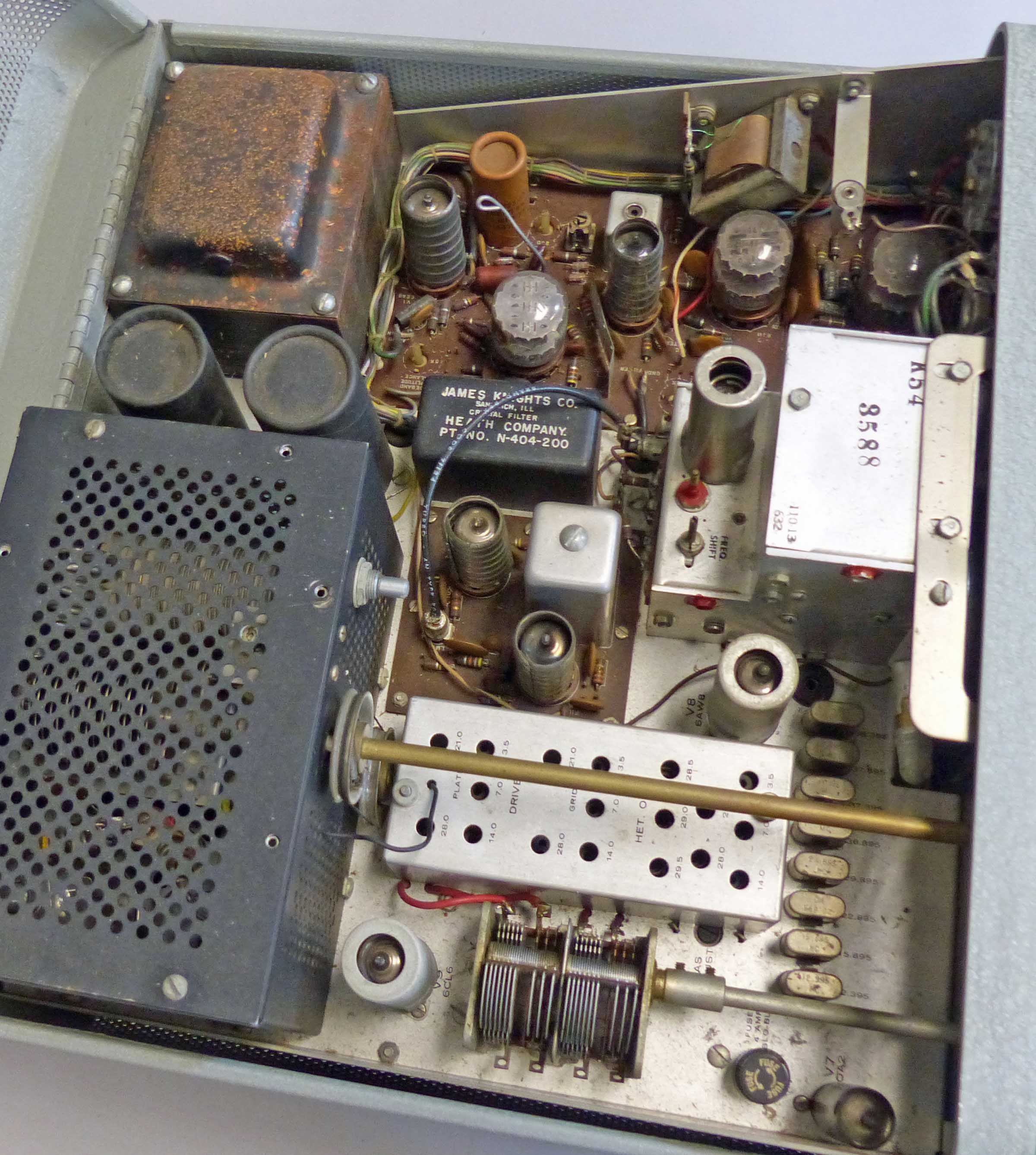
The SB-400 is designed around 12 tubes including three compactors and a pair of 6146 finals, and although two PC boards were used, there is still great deal of point-to-point wiring.
The 400 will run USB, LSB, and CW, but has no provision for AM; employs a 2.1 kHz crystal filter, and covers 500 kHz portions of the 80 through 10 meter amateur bands. Ten meters is covered in four 500 kHz segments.
DC power input is about 180 watts PEP SSB and about 170 watts CW. RF power output is about 100 watts from 80 through 15 meters and about 80 watts on 10. The finals are fully neutralized and are run in class AB1.
Features include PTT or VOX operation, break-in CW (but not QSK), a built-in T/R relay (mechanical), Heath’s standard LMO, a spotting function, and a built-in solid state power supply. For additional discussion of the LMO, refer to SB-100.
It is interesting to note that while the operator can always choose to key the transmitter by pushing the PTT button on the mic, the VOX circuit is always active. There is no way to shut off the VOX short of turning the VOX sensitivity control (inside the cabinet) all the way down. It should also be noted that while Heath refers to the 400 as having “break-in” CW, it isn’t QSK. CW keying works by keying the VOX with a built-in side-tone. The sidetone is also fed to the SB-300’s audio line where it is used to monitor sending.
The SB-400 can be configured to work separately from the SB-300 or to transceive with it. In the transceive mode, the SB-300 determines the operating frequency.
Switching from separate operation to transceive requires changing a couple of cables inside the SB-400. This clumsy chore was streamlined in the SB-401.
The SB-400 is supplied with all needed heterodyne oscillator crystals so it can be used with any other make or model of receiver. Refer to SB-301 for SB-400/401interconnection diagram.
The front panel is a mirror image of the SB-300. The panel meter is on the right, and the placement of the controls is likewise reversed. Front panel controls include driver tune, loading, function, main tuning, zero set, mic/CW level, meter function, and mode.
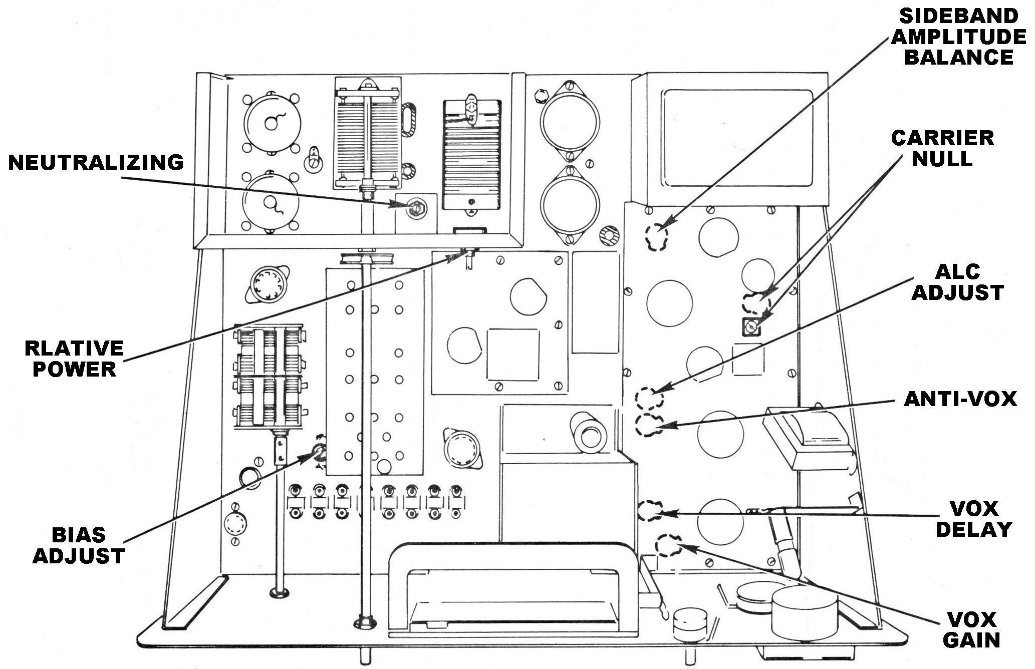
Internal controls include neutralizing, relative power adjust, bias adjust, sideband amplitude balance, carrier null, ALC adjust, sidetone output, and VOX controls.
Rear panel connections include a quarter inch key jack, RCA jacks for receiver audio input, 8Ω speaker output, anti-VOX, receiver mute, and receiver antenna output. There is also an SO-239 connector for a 50-75Ω antenna, a ground post, and a 120 VAC standard two-blade receptacle used to power an external antenna relay.
Note: because of the different size and mounting hole configurations, SB-400 and 401 crystal filters are mutually incompatible.
Alignment requires a dummy load, a VTVM with an RF probe, and a CW key.
References
Review. 73 Amateur Radio. Sep 1964, p. 64.
Review. CQ. Dec 1964, p. 54.
Review. QST. Jan 1965, p. 54.
Full break-in without keying VOX. QST. Jul 1965, p. 80.
No LSB (brief). CQ. Oct 1965 p. 74.
Adding a switch for working split. 73 Amateur Radio. Nov 1966, p. 74
Improved switching from transmit to transceive. QST. Dec 1966, p. 21.
Improved spotting. QST. Nov 1968, p. 51.
Operation outside the ham bands. CQ. Jan 1969, p. 96.
VOX adjustment. QST. Dec 1971, p. 40.
Increase friction in worn zero set. QST. Jan 1973, p. 52.
Faster relay response. QST. Feb 1977, p. 43.
Zero-set dial modification. QST. Feb 1980, p. 44.
Power supply upgrade. Electric Radio. Apr 2007.
Improved ALC response. Ham Radio. Jan 1970, p. 71.
General information about SB series. Electric Radio. Sep 2016.
Frequency range (in MHz): 3.5–4.0, 7.0–7.5, 14.0–14.4, 21.0–21.5, 28.0–28.5, 28.5–29.0, 29.0–29.5, 29.5–30.0
Stability: < 100 Hz per hour after 20 minutes warmup; < 100 Hz for ±10% line voltage variation.
Emission types: LSB, USB, CW
DC input power:
SSB: 180 watts PEP
CW: 170 watts
RF output power:
80–15 meters: 100 watts
10 meters: 80 watts
Output impedance: 50–75Ω
Visual dial accuracy: within 200 Hz on all bands
Electrical dial accuracy: within 400 Hz on all bands after calibration to nearest 100 kHz point
Backlash: < 50 Hz
Carrier suppression: 55 db down from rated output
Oscillator feedthrough or mixer products: 55 db below rated output (except at 3910 kHz crossover which is 45 db)
Harmonic radiation: 35 db below rated output
Unwanted sideband suppression: 55 db down from rated output at 1000 Hz and higher
Third order distortion: 30 db down from rated PEP output
Noise level: at least 40 db below rated carrier
Audio frequency response: 350–2450 Hz ±3 db
Audio compression: 10 db nominal at 0.20 mA final grid current
Audio input: high impedance or phone patch
CW sidetone: internally switched to speaker with transmitter in CW mode and key depressed; about 1000 Hz
Keying: break-in CW, provided by operating VOX from keyed tone, using grid block keying
Power requirements: 120/240 VAC, 50/60 Hz; 80 watts standby, 260 watts key down
Tubes: (1) 0A2, (1) 6AU6, (1) 6AV11, (1) 6AW8, (1) 6CL6, (1) 6D10, (1) 6EA8, (2) 6EW6, (1) 6J11, (2) 6146
Photos, general information and specifications from "Heathkit: A Guide to the Amateur Radio Products," by Chuck Penson, WA7ZZE. Used with permission.