Note
With the famous HW-30 “Lunch Box,” Heath had had a signal on 2-meters since 1960, but in 1968, the HW-17 was Heath’s first serious foray into the soon-to-be-booming world of VHF. It wouldn’t be fair to say that the HW-17 was fraught with problems—but it was not entirely successful.
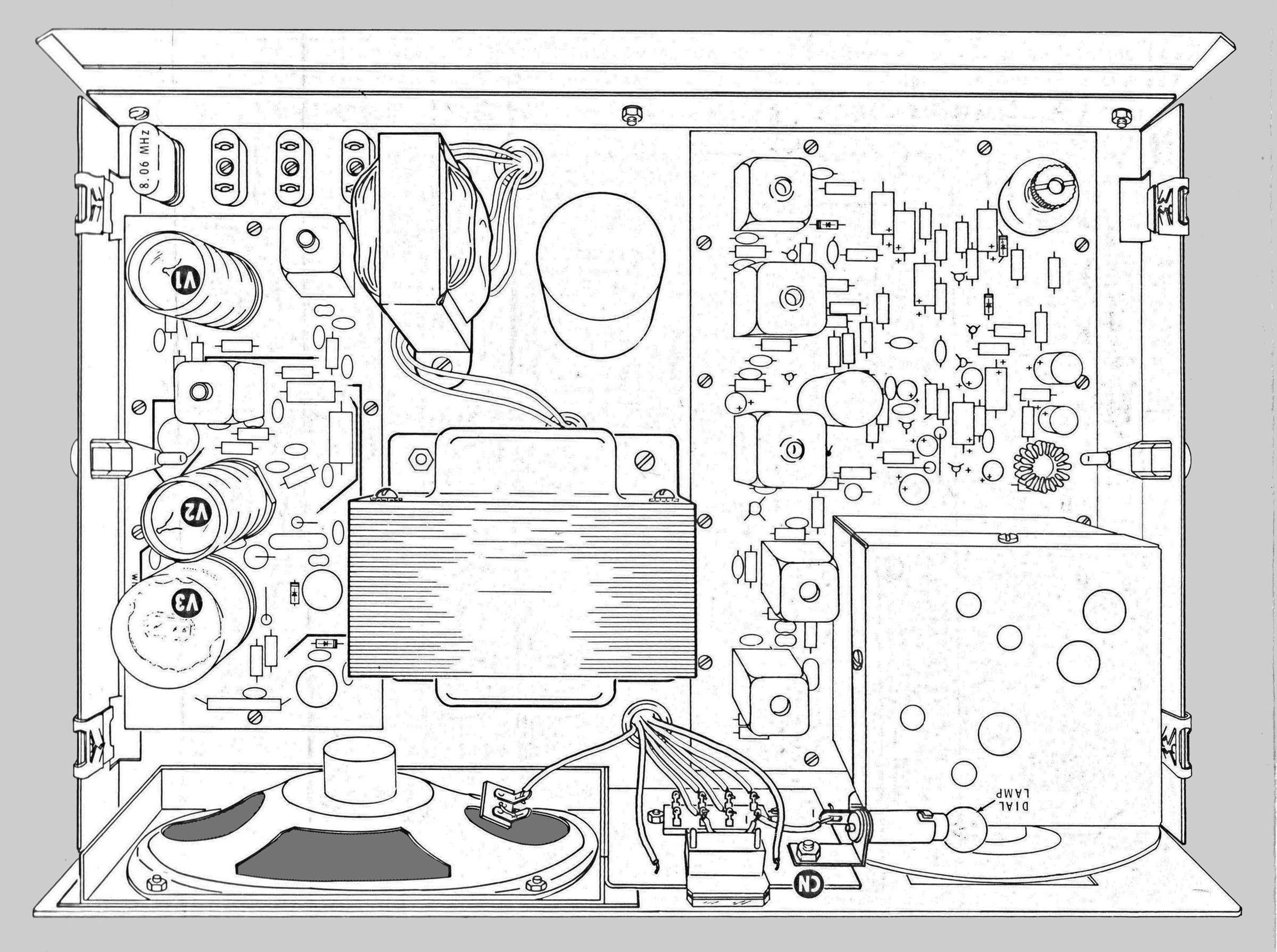
The HW-17 is not a true transceiver since it has completely separate circuits for its crystal-controlled tube-type transmitter and tunable transistorized receiver. These two sections share a common solid state power supply.
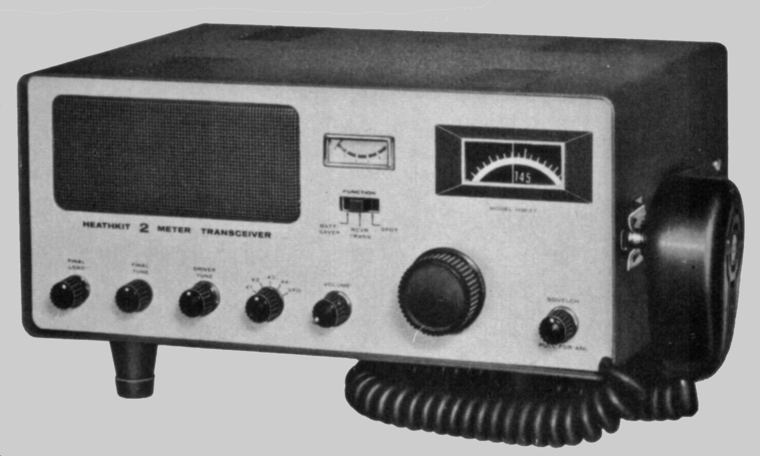
Front panel controls include final load, final tune, driver tune, crystal/VFO selector, on/off/ volume, squelch/ANL, function switch, and main tuning. The front panel also sports a meter that reads S-units and relative power. Supplied with a Turner 350C microphone hard-wired to the transceiver.
The 3-tube transmitter provides about 10 watts of AM output between 143.2 and 148.2 MHz with an 8156 final amp. It can operate on one of four switch-selected crystal frequencies or can be controlled by an external VFO (like the HG-10 or 10B). In addition to the ham band, the HW-17’s frequency coverage permits operation on CAP, MARS, and Coast Guard Auxiliary channels. The HW-17 was supplied with one crystal (8060 kHz, which equals 145.080 MHz).
The fully solid state receiver is a tunable dual-conversion superhet design using a pre-assembled and pre-tuned tuner with an N-channel junction FET. Sensitivity is rated at 1.0 µV, with a selectivity of 27 kHz at 6 dB down.
Features of the HW-17 include PC board construction, a built-in 120 VAC power supply, electronic T/R switching, fixed mic gain level, squelch, noise limiter, a combination relative power and S meter, a lighted dial, spotting switch, a built-in speaker and a battery saver function (powers only the receiver section and draws just 100 mA). Note that 12 VDC operation requires the HWA-17-1 mobile power supply (listed separately), or (simpler yet) a modern sine wave power inverter.
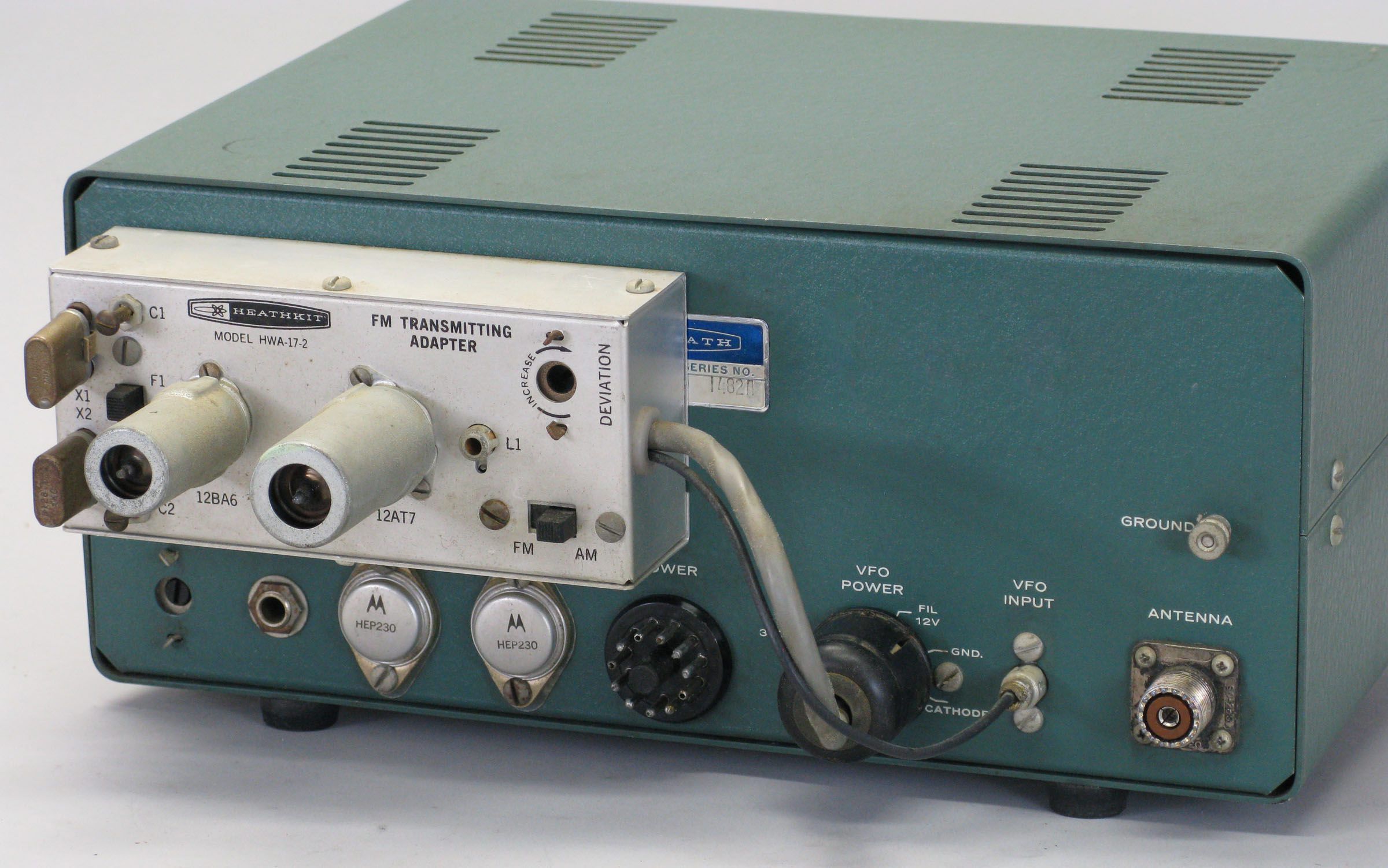
The only rear panel control is a meter zero adjustment. Rear panel connections include RCA jacks for a VFO and a 50-75Ω antenna, an 11-pin power socket for a VFO, octal power plug for power input, and a quarter inch headphone jack. The HW-17 was offered with an optional DC power supply (HWA-17-1) and an optional FM adapter (HWA-17-2)—a tube-type unit that mounted outboard on the rear panel.
The HW-17 had a number of problems that Heath attempted to rectify with the release of the HW-17A. These problems included low audio on the transmitter, a spot signal that was far too strong, very poor AGC, a useless noise blanker, microphonics, poor receiver sensitivity, and an FM adapter that didn’t work very well. HW-17 owners were offered two separate modification kits to help solve their problems. Although they tried diligently, Heath’s engineers never completely solved all the troubles of the HW-17A.
The kit never sold very well and was discontinued after three years on the market. The HW-17 and 17A can be aligned without instruments, are housed in a tone-tone green cabinet and use dark green knobs. Originally supplied with a tilt mounting bracket for mobile use (almost always missing today). Beware the fused power plug.
CRYSTAL FREQUENCY CALCULATION
operating frequency / 18 = crystal frequency
Crystal specifications:
C loading: 29.7 pF
Drive level: 15 mA @ 13Ω
Effective resistance: 25Ω
One HC-6/U socket and three FT-243 sockets are provided.
FOR USE WITH HG-10(B) VFO
An octal socket on the back on the HW-17 provides power for an external VFO. Two small modifications are required to use the HG-10(B) VFO with the HW-17.
First, an 8Ω, 10 watt resistor must be connected in series with the filament line to the VFO. This is required to drop the 12-volt transceiver filament voltage to the 6-volt filament voltage of the VFO.
Second, the HG-10(B) must be wired for cathode keying. Refer to the HG-10(B) or the HG-10(B) assembly manual.
Any VFO used with the HW-17 must have an output in the 8000 to 8222 kHz range.
MODIFICATIONS
A factory authorized modification was designed to fix several issues with the HW-17. These included improved stability of the final amplifier under varying load conditions, improved modulation percentage, reduced spotting level, and reduced residual hum and noise in the receiver.
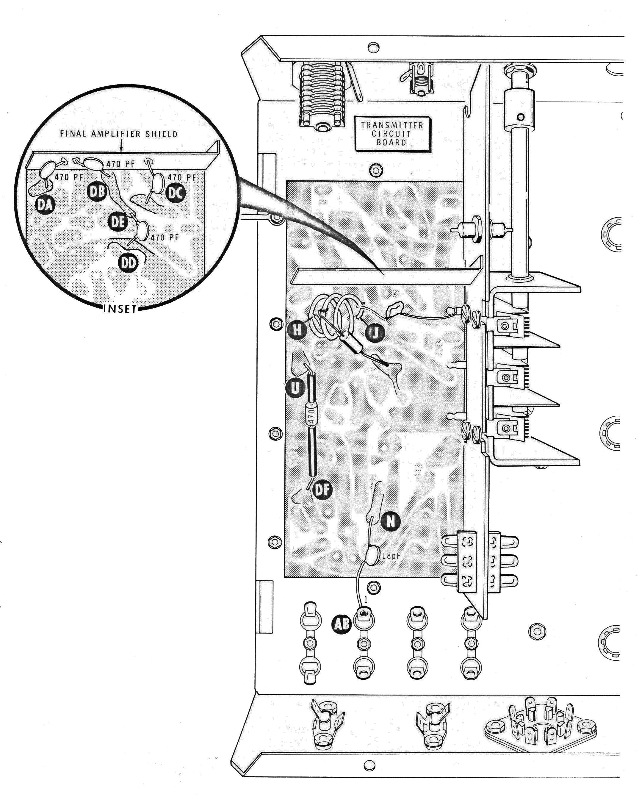
The modification involved a significant number of board-level component changes that would be difficult to spot easily. But it also involved the installation of additional components on the foil side of the transmitter circuit board, and these components are easy to see.
Refer to Pictorial A. Remove the HW-17 from its cabinet and look at the foil side of the transmitter circuit board. Check for the presence of added capacitors at DA, DB, DC, DD and DE as shown in the inset. Also check for an added capacitor between points AB and N.
Note: The coil and components near H and J, and the resistor between points DF and U are pre-existing parts.
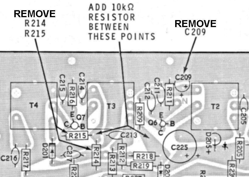
Heath suggested two other modifications for the HW-17—one to improve squelch operation, and the other for improved AGC action. These are circuit board level modifications that are more difficult to detect. Figure 1 is a detail of the receiver circuit board seen from the component side, and will provide some guidance for the detection of the squelch and AGC modifications. Note: the 10kΩ resistor should be installed on the foil side of the board.
A modification of the HW-17 is also required for use with the HWA-17-2 FM adapter. Refer to HWA-17-2 for discussion and specifications.
References:
Review (HW-17A). QST. Jul 1969, p. 49.
Increased sensitivity and output (HW-17A). QST. Apr 1970, p. 38.
Improvements. Ham Radio. Aug 1970, p. 70.
Better sensitivity. Ham Radio. Mar 1971, p. 66.
Modification for FM (HW-17A). CQ. Feb 1972, p. 14.
Improvements. Electric Radio. Jun 2014
Transmitter section
Frequency coverage: 143.2 to 148.2 MHz
Power input: 25 to 30 watts
Power output: 8 to 10 watts into a 50Ω non-inductive load
Transmitter mode: A3 (AM)
Modulation capability: automatically limited to less than 100%
Frequency control: crystal or external VFO; supplied with one crystal (8060 kHz)
Crystal sockets: (1) HC-6U, (3) FT-243
Crystal multiplication: 18 times
Receiver section
Frequency coverage: 143.2 to 148.2 MHz
Receiving mode: A3 (AM)
Sensitivity: better than 1.0 µV for 10 db signal-plus-noise to noise ratio (30% modulation @ 400 Hz)
IF selectivity: 27 kHz @ 6 db down
IF: 26.51 and 2.0 MHz
Antenna input impedance: 50 to 72Ω, unbalanced
Audio output power: 1 watt @ less than 10% distortion
Audio output impedance: 3.2Ω (speaker or headphones)
Dial calibration: every 100 kHz
Temperature range: –5 to +120 F
Power requirements: 120/240 VAC, 50/60 Hz, 100 watts maximum
Size: 14.25 wide x 6.25 high x 8.5 deep: Weight: 13 lbs
Tubes: (1) 12GN7, (1) 7095, (1) 8156
Transistors: (2) UC734, (1) SE5023, (4) 2N3694, (4) 2N3393, (1) X29A829, (2) 40050
Photos, general information and specifications from "Heathkit: A Guide to the Amateur Radio Products," by Chuck Penson, WA7ZZE. Used with permission.