Note
GC-1 1959-1960 $99.50
GC-1A 1960-1968 $89.50
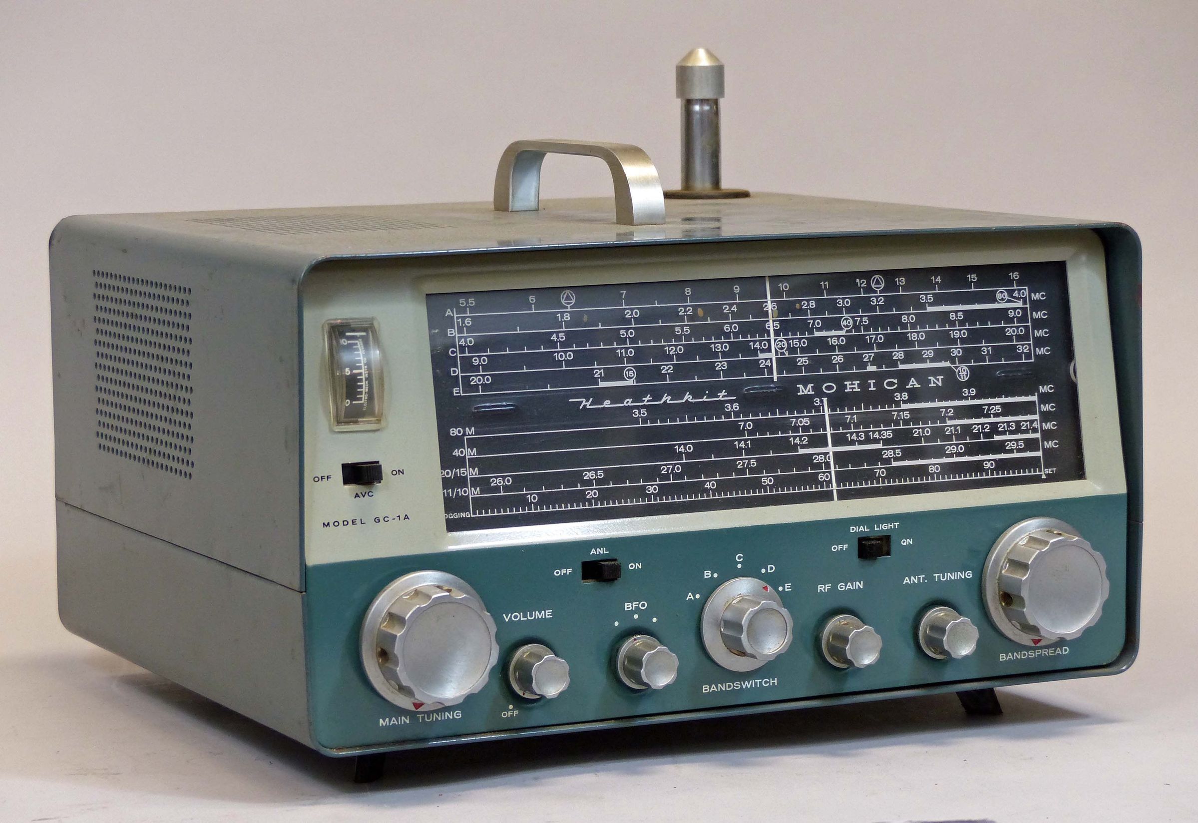
The GC-1 "Mohican” was Heathkit’s first solid state SWL receiver and the first ever commercially available, fully solid-state SWL receiver on the market. The GC-1 was introduced late in 1959 and was sold for less than a year before being replaced with the GC-1A. Originally priced at $99.95, the 1A went to $109.95. But by 1968, Heath had sold so many that it were able to reduce the price to only $89.50, having recouped its development costs many times over by then. And while official withdrawn from the catalog after 1968, it was still available for a few more years as a kind of unadvertised special, if you asked for it.
The GC-1 and 1A receivers were designed to be portable but weigh 17 pounds, so you probably are not going to carry them very far. A nice feature was that the carrying handle could be installed on top or the side of the cabinet.
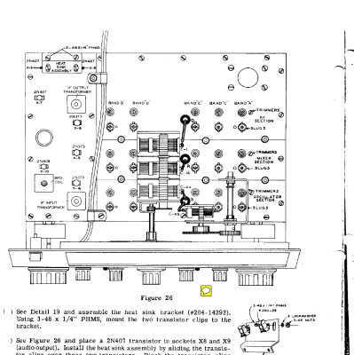
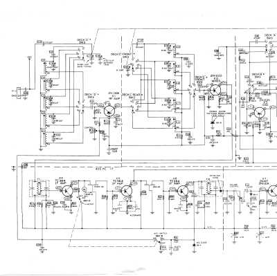
The circuit uses 10 socket-mounted germanium PNP transistors, and 6 diodes. These are all common devices with modern-day NTE replacements. A seventh diode (not listed in the parts list) is used as part of transformer T2. The receiver is a single conversion, superhet design with a 455 kHz IF, and covers from 550 kHz to 32 MHz in five bands. Much of the electronics are on a single printed circuit board, but a great deal of point-to-point wire still exists.
The upper half of the tuning dial is divided into five bands and has calibration marks used to set the main tuning correctly so that the lower half of the dial, which is a band spread for the amateur bands, reads correctly.
The unit features a BFO for SSB and CW reception, an AVC, a noise limiter, switchable dial illumination, and sports a gigantic 54-inch telescoping antenna. There are also connections for muting, external antenna, and headphones.
An unusual design feature of the CG-1(A) is the use of a positive ground. Another is it’s 35Ω speaker, for which a replacement may be impossible to find.
DIFFERENCES BETWEEN THE GC-1 and GC-1A
Compiled by Bob Eckweiler, AF6C
There are a number of circuit changes between the GC-1 and GC-1A. Some of the early GC-1 units had trouble with audio distortion when the batteries began to get low, or when the receiver got hot. And there were some issues with instability at higher frequencies. The GC-1A resolved all of these problems, and Heath issued a modification kit for owners of the GC-1.
• The dial light circuit was changed to reduce current draw. Bulbs were changed from #47 lamps (6.3V @150 ma) to #49 lamps (2.0V @ 60 ma).
• The band switch was changed. Deck ‘B’ was changed so it could short out the unused oscillator coils.
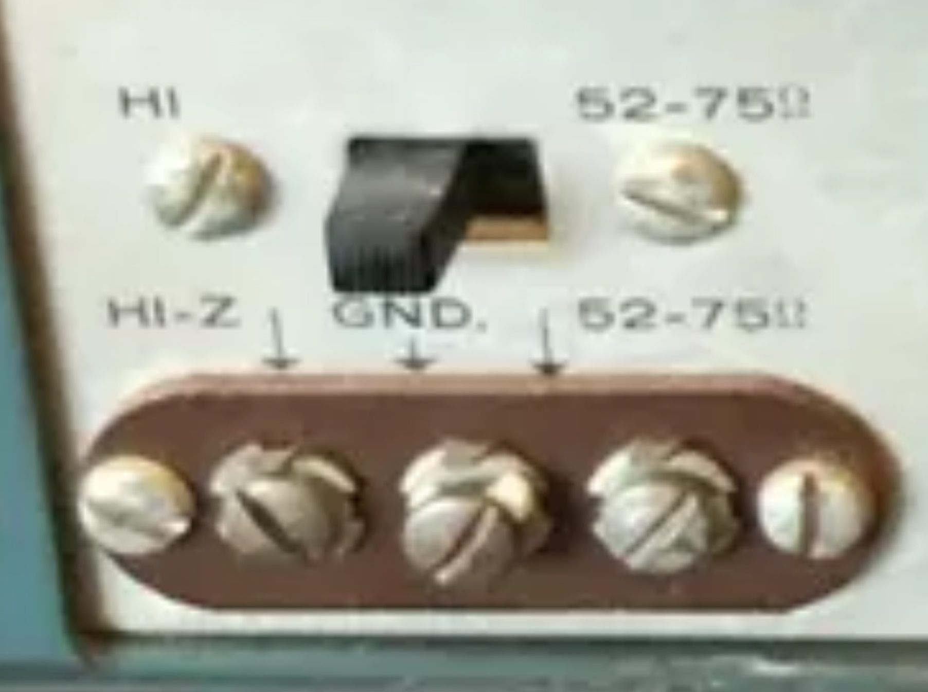
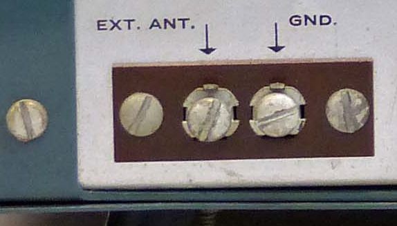
• The 50 Ω antenna input and switch to select either 50 Ω or HI-Z antenna input was removed. The GC-1A only has the HI-Z input. The rear screw terminal board was reduced from three to two terminals (Was HI-Z, GND., 52-75Ω – Is EXT.- ANT., GND.)
• A zener diode was added for voltage regulation of the HF oscillator and BFO.
• The audio output circuit was stabilized with the replacement of R40 and R42 with 1N2326 com-pensation diodes.
• The RF Gain control was changed from a linear 20 KΩ potentiometer to a 10K audio taper potentiometer to give better control.
• The BFO coupling capacitor was changed from 1.0 μμf to 4.7 μμf to increase the strength of the BFO for improved CW and SSB reception.
• The 2N373 transistors used in the IF were replaced with Texas Instruments type TI364. (Probably an issue of cost and availability, rather than performance.) Al other solid state remains unchanged.
Here are some things that haven NOT changed:
• No change was made in the circuit board between models. It still uses the same part #, which probably means it does’t show component values.
• While three diodes were added, the remaining semiconductors (transistors and crystal diodes) remained the same. All the transformers and coils remain the same.
A small detail: On the GC-1A, the model number appears under the AVC switch on the left side of the front panel. On the GC-1, no model number appears.
The Mohican’s flywheel tuning gave it a very smooth, solid feel and its heavy gauge metal cabinet lent to the overall feeling of a rugged piece of gear. The GC-1 and 1A came standard with a battery power pack requiring 8 “C” cells and was offered with an optional XP-2 120 VAC adapter. The battery pack and the AC adapter are interchangeable and fit into a compartment on the receiver’s rear panel.
The GC-1 and 1A are rated at 10 µV on the broadcast band and 2.0 µV elsewhere.
The GC-1A was replaced by the GR-78 in 1969. An argument can be made that the Mohican was the best SWL receiver Heath ever made—tube or transistor—surpassed only by the SB-303 and 313 (which are not general coverage receivers), and probably the GR-78. The unit’s compact size (by the standards of the day), battery power supply, and use of commonly available batteries, made it extremely popular, especially with those traveling overseas. The Mohican was so popular in fact that sales of it continued for almost five years after it was withdrawn from the catalog.
Note: For normal operation, a jumper wire should be placed across the MUTE terminals. Opening the mute terminals removes the –12 VDC supply, cutting power to the receiver, but not the panel lights.
The GC-1 and 1A are “Heath green” in color. Early units where supplied with brushed chrome knobs. Later units had polished chrome knobs.
References:
Review, 73 Amateur Radio. Oct 1960, p. 38.
Review. QST. Dec 1960, p. 32.
Review. CQ. May 1962, p. 44.
Converter for 2 meters. CQ. Jan 1961, p. 72.
Improved noise limiter. QST. Jul 1962, p. 53.
Use with wide band pre-amp. CQ. Aug 1969, p. 79.
Review. Electric Radio. Sep 2015.
Frequency coverage: 550 kHz to 32 MHz in five bands
Selectivity: 3 kHz wide @ 6 db down
Selectivity:
550 to 1600 kHz: 10 µV, 10 db or better signal to noise
1600 kHz to 32 MHz: 2.0 µV, 10 db or better signal to noise
Battery life: “up to 400 hours normal intermittent service”
Audio output: 400 milliwatts at 10% distortion
Power requirements: 12 volts @ 35 mA with 50 milliwatts audio output
Size: 6.875 high x 12 wide x 10 dee; Weight: 17 lbs
Solid-State (GC-1A): (1) 2N1396, (2) 2N1225, (3) TI364, (3) 2N407, (1) 2N409, (2) 1N2326, (1) 1N754 Zener, (3) HD2257 germanium diode
Optional XP-2 AC Power Supply
Output: 12 VDC nominal, 200 mA maximum
Pin-out connections:
pins 3 and 4: +12 VDC
pins 5, 6, an 7: –12 VDC
pins 1 and 9: AC switch
Duty cycle: continuous
Ripple: 0.3% at 150 mA
Fuse: 1/8 amp soldered-in on transformer primary
Power requirements: 120 VAC, 50/60 Hz, 3.5 watts
Photos, general information and specifications from "Heathkit: A Guide to the Amateur Radio Products," by Chuck Penson, WA7ZZE. Used with permission.