Note
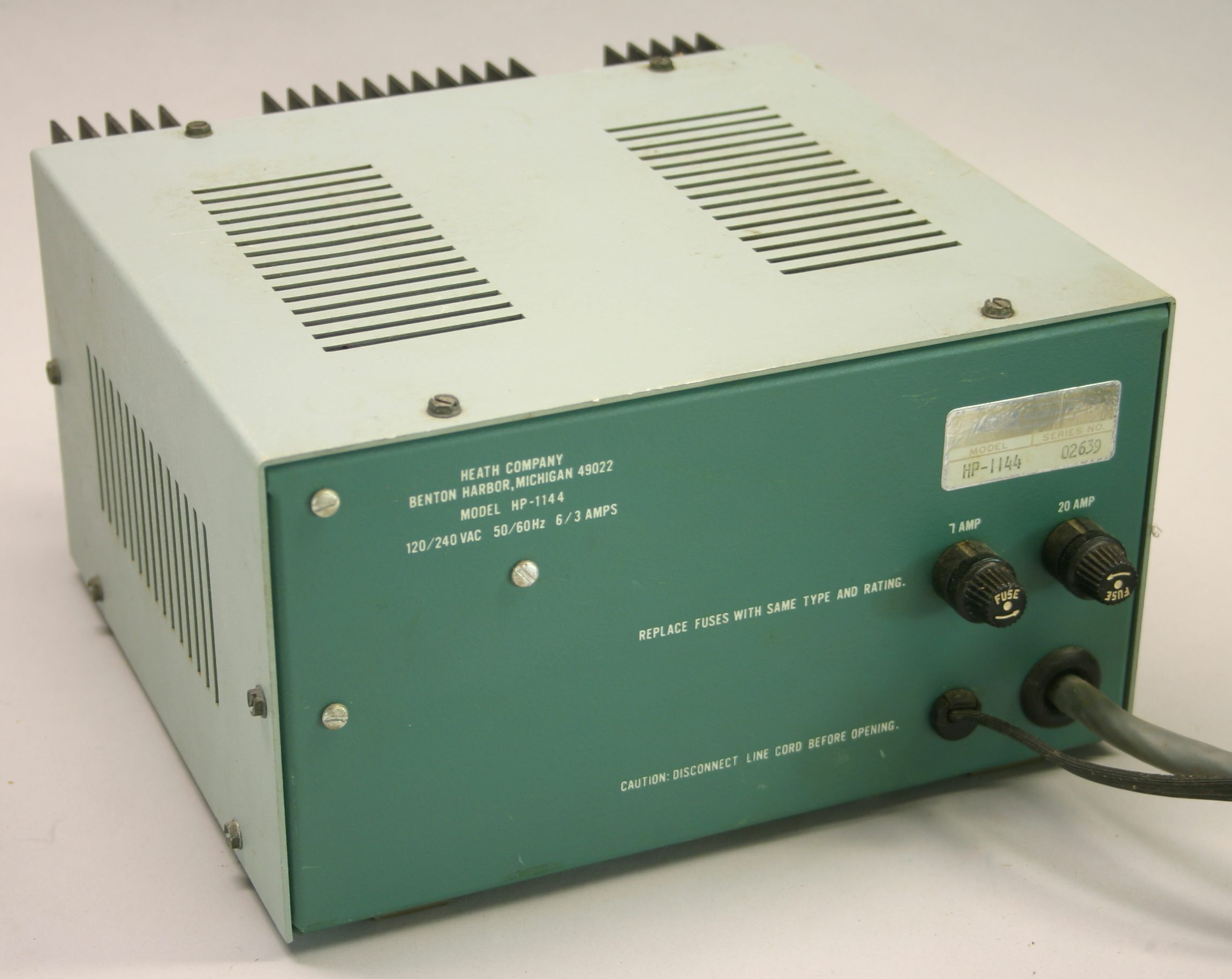
The HP-1144 and PS-1144 power supplies were designed for use with the SB-104 and HW-104, and were outwardly indistinguishable from each other. The blue and white label will identify the units. The basic specifications for both versions are identical, and both use a full-wave rectifier and “triple Darlington regulation."
The difference between the HP-1144 and the HP-1144A / PS-1144 is the addition of an over-voltage protection circuit, referred to as a crowbar circuit.
The SB-104 could be damaged by input voltages exceeding 15.5 volts, and if certain parts in the power supply failed, the voltage could spike to about 28 volts. To protect the SB-104 from excessive input voltage, the crowbar circuit would blow the HP-1144A's DC-side fuse if the output voltage rose above 15.5 VDC.
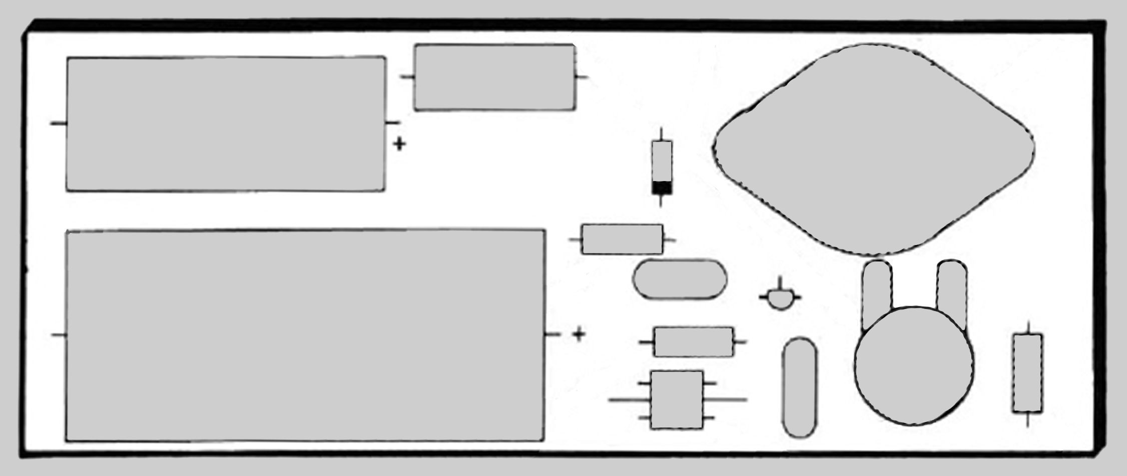
A modification kit was offered to owners of the HP-1144. The modification involved the assembly and installation of a completely new circuit board, and installation of new pass transistor, so it was virtually a complete rebuild of the power supply. It is easy to tell if the new PC board has been installed. Refer to illustrations to identify distinguishing characteristics.
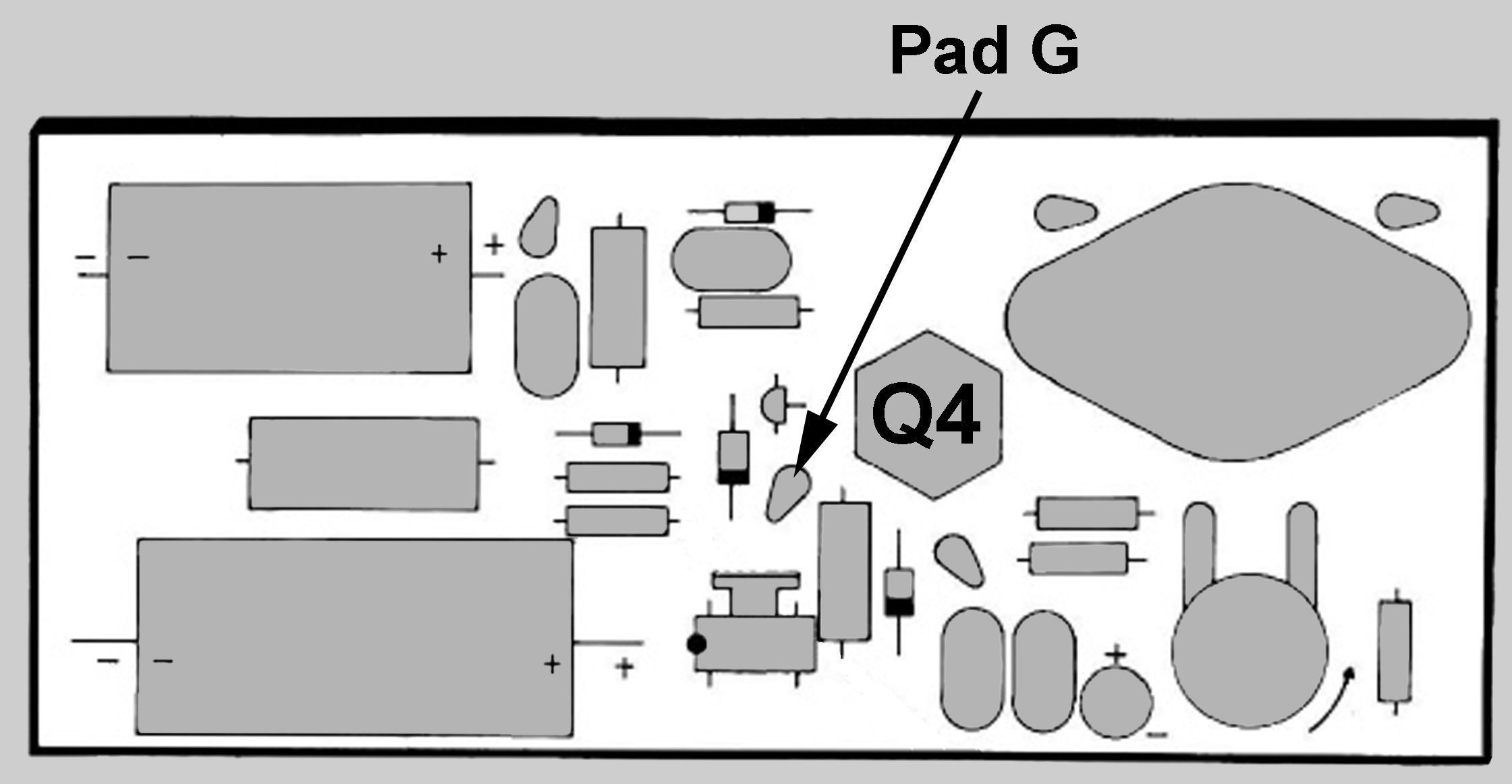
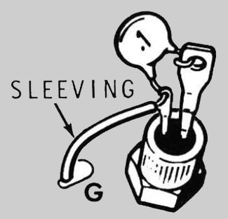
While the crowbar circuit provided ample protection for the radio, it introduced a new problem—rectification of RF. Strong RF fields on voice peaks could trip the crowbar and blow the fuse. Fortunately, this annoying problem was easily solved with the addition of a 0.1 uF bypass capacitor (designated C11) installed between the anode and gate of SCR Q4. A modification was sent to existing customers, and the fix was incorporated into kits shipped after November 1978. Refer to illustrations.
Note: The assembly manual with part number 595-2198 was published prior to the addition of C11. The revised assembly manual, part number 595-2198-01, includes C11 but the part is not shown on the schematic. Instead, Heath included an errata sheet with instructions to add C11 to the schematic by hand. Refer to illustration for the location of C11 on the schematic.
PS-1144 is identical to the HP-1144A. The model number change was precipitated by a complaint from Hewlett Packard.
Caution: On the HP-1144A and PS-1144 versions it is possible to blow the DC-side fuse by adjusting the output voltage adjustment control (located on the PC board) to too high a voltage. It should be set it to 13.8 volts.
These power supplies are designed to fit inside the SB-604 speaker.
Output voltage: 13.8 VDC, adjustable from about 11 to 16 volts
Regulation: 2% from zero to 20 amps
Output current: 8 amps continuous, 20 amps intermittent.
Ripple: 1% at 20 amps
Fuses:
primary side: 7 amp, 3AG, slow-blow
DC side: 20 amp, 3AG
Power requirements: 120 VAC at 6 amps, or 240 VAC at 3 amps, 50/60 Hz
Photos, general information and specifications from "Heathkit: A Guide to the Amateur Radio Products," by Chuck Penson, WA7ZZE. Used with permission.