Note
QST, Dec 1961, p. 163.
QST, Sep 1963, p. 155.
QST, Jan 1964, p. 157.
The Telewriter Model K is a tube-based audio frequency shift converter designed and manufactured by Alltronics-Howard Co. of Boston, Massachusetts. It serves as an interface between a radio receiver and a teleprinter (or other DC pulse devices), converting audio frequency-shift keying (AFSK) tones into DC loop pulses.
Primary Function: Receives audio frequency-shift tones centered at 2550 Hz (with shifts ranging from 100 Hz to 1000 Hz, typically standard 850 Hz shift) from a radio receiver's audio output and converts them to DC pulses to drive a teletype printer. The Model K uses a self-contained DC loop power supply to drive printer magnets directly via a vacuum tube keyer, isolating the DC loop from local radio noise.
Tube Lineup
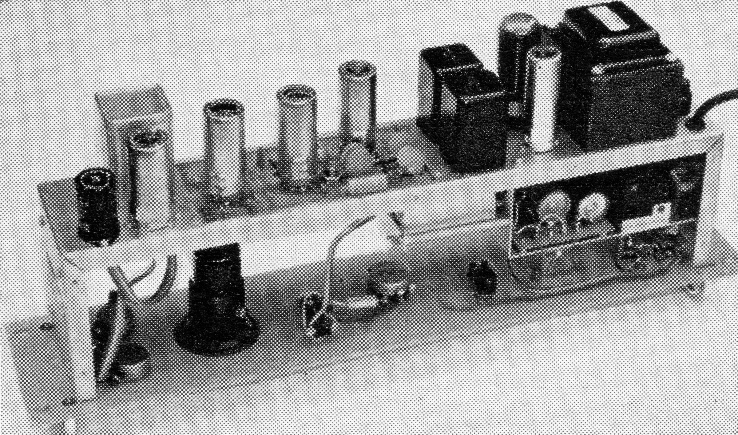
– 12AX7: A two-stage limiter amplifier that normalizes signal amplitudes, allowing weaker signals to be printed reliably.
– 12AX7 and 1N69 Diodes: A linear discriminator amplifier and rectifier circuit that handles standard 850-Hz shifts as well as narrow shifts. Low-pass filtering follows to eliminate high-frequency noise and beat notes.
– 12AX7: A symmetrical pulse clipper and DC amplifier that slices the filtered pulses to eliminate distortion and beat frequencies riding on the signal.
– 6W6: The final keyer tube stage driving the printing loop directly. This electronic keying approach prevents the radio noise common in relay-keyed circuits.
– 12AX7 and 6AF6: An indicator amplifier driving a dual magic-eye tuning tube for precise visual signal tuning.
– 6X4: Functions as the high-voltage rectifier, accompanied by a diode bias rectifier. The internal 120 V DC supply for the printer and keyer tube operates independently from the main plate supply, allowing the printer loop to be grounded.
– 6AF6: Dual magic-eye tube configured so that the "mark" eye closes on a 2125 Hz signal and the "space" eye closes on a 2975 Hz signal.
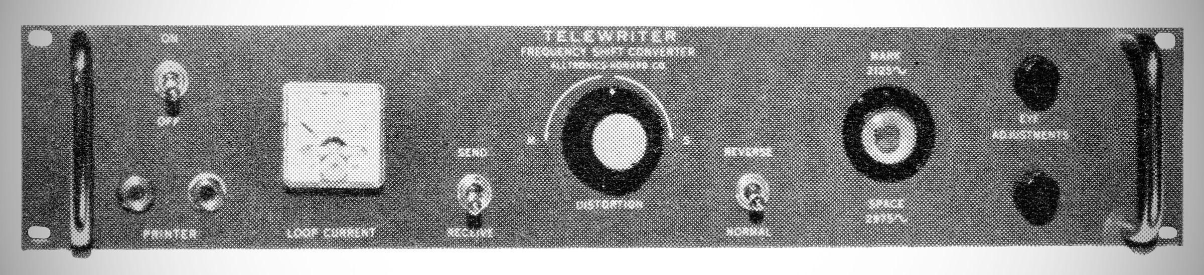
A center-panel rotary knob adjusts the weight of mark or space pulses to compensate for propagation anomalies.
Features a front-panel meter to monitor loop current, which is adjustable (typically to 30 or 60 mA) via an internal slider resistor.
Switching & Jacks: Includes power, Send-Receive, and Reverse switches (the latter flips mark and space if the signal is inverted). Two series-connected, closed-circuit jacks on the front panel allow simultaneous operation of a printer and a reperforator.
Transmitting Provisions: Includes an octal socket for an optional internal polar relay, along with a rear-panel output plug to drive external relays or additional loop circuits during transmission.
Specifications
– Input Impedance: 600 ohms
– Input Level: –33 to +30 dBm} (ref 1 mW}
– Frequency Shift Range: 100 to 1000 Hz) (Center frequency 2550 Hz}
– Output Pulse: Neutral DC pulses, 60 mA into 0--5000 ohm load
– Keying Speed: Up to 100 wpm max
– Metering: Front-panel 0–100 mA DC meter
– Tuning Indicator: 6AF6 dual-electron tuning eye tube
Note: Offered with an optional CRT to replace the eye tube. See, for example, 73 magazine, Feb 1964, p.55) Adds $80 to the price.
Tube Complement (7 total)
– 12AX7: Limiter / Amplifier
– 12AX7: Discriminator Driver
– 12AX7: Pulse Clipper & DC Amplifier
– 6W6: Keyer Tube
– 12AX7: Tuning Indicator Driver
– 6AF6: Dual Electron Tuning Indicator Eye
– 6X4: Power Supply Rectifier
Power Requirements: 115 VAC, 60 Hz, 50 watts
References
Review: QST, Jun 1962, p. 54.