Note
QST, Jul 1961 p. 126.
QST, Dec 1963, p. 133.
QST, Jan 1964, p. 127.
QST, Feb 1965, p. 137.
QST, Jan 1966, p. 113.
QST, Jan 1967, p. 5.
Ameco catalog #5, 1967
QST, Jan 1968, p.5
QST, Mar 1969, p. 5.
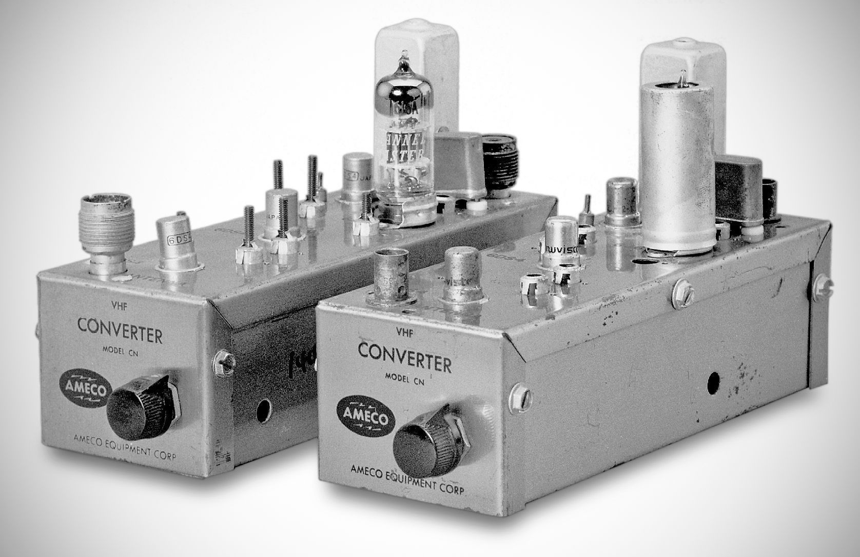
The Ameco Converter, Model CN, is a crystal-controlled broadband converter with a very low noise figure, very high gain and excellent image and spurious rejection. When used in conjunction with a receiver, it will provide reception of the desired VHF amateur band. The CN-50 covers 50-54 MHz., the CN-144 covers 144 to 148 MHz. and the CN-220 covers 220 to 225 MHz.
The converter uses a type 6CW4 or 6DS4 Nuvistor tube as the first RF amplifier, a 6CW4 or 6DS4 Nuvistor as the second RF amplifier and a 6CW4 or 6DS4 as the mixer. A 6J6 serves as the crystal controlled oscillator and multiplier. The circuitry used, together with considerable internal shielding and bypassing, provide high sensitivity to the desired signals and maximum rejection of spurious, undesired signals. A novel feature of this unit is the fact that the output frequency may be changed quite ile simply. This feature prevents the converter from becoming obsolete when the receiver is changed to a different type.
The MARS and CAP frequencies near the 2-meter band are also covered with the CN-144 converter.
Specifications
– Noise figure:
50 MC. 2.5 db
144 MC. 3.0 db.
220 MC. 4.0 db.
– Gain: 45 db. average.
–Image and spurious rejection: better than 70 db.
Power requirements: 100-150 volts at 30 ma
Filament requirements: 6.3 volts at 0.85 amps
Tube lineup: First rf amplifier - 6DS4 Nuvistor, second rf amplifier - 6DS4 Nuvistor, mixer - 6DS4 Nuvistor, oscillator 6J6.
The following tables will provide a quick reference for 2 meter and 6 meter units for identification of the received band and IF output, based on the crystal frequency.
To Receive IF Output (MHz) Crystal (MHz)
144-148 7-11 45.6667
144-148 10-14 44.6667
144-148 14-18 43.3333
144-148 26-30 39.3333
144-148 28-32 38.6667
144-148 30.5-34.5 37.8333
144-148 50-54 31.3333
144-145 600-1600 kHz 47.8000
145-146 600-1600 kHz. 48.1333
146-147 600-1600 kHz 48.4667
To Receive (MHz) IF Output (MHz) Crystal (MHz)
50-54 7-11 43
50-54 10-14 40
50-54 14-18 36
50-54 26-30 24
50-54 28-32 22
50-54 30.5-34.5 19.5
50-51 600-1600 kHz 49.4
51-52 600-1600 kHz 50.4