Note
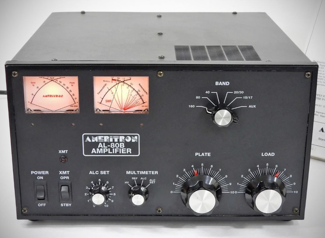
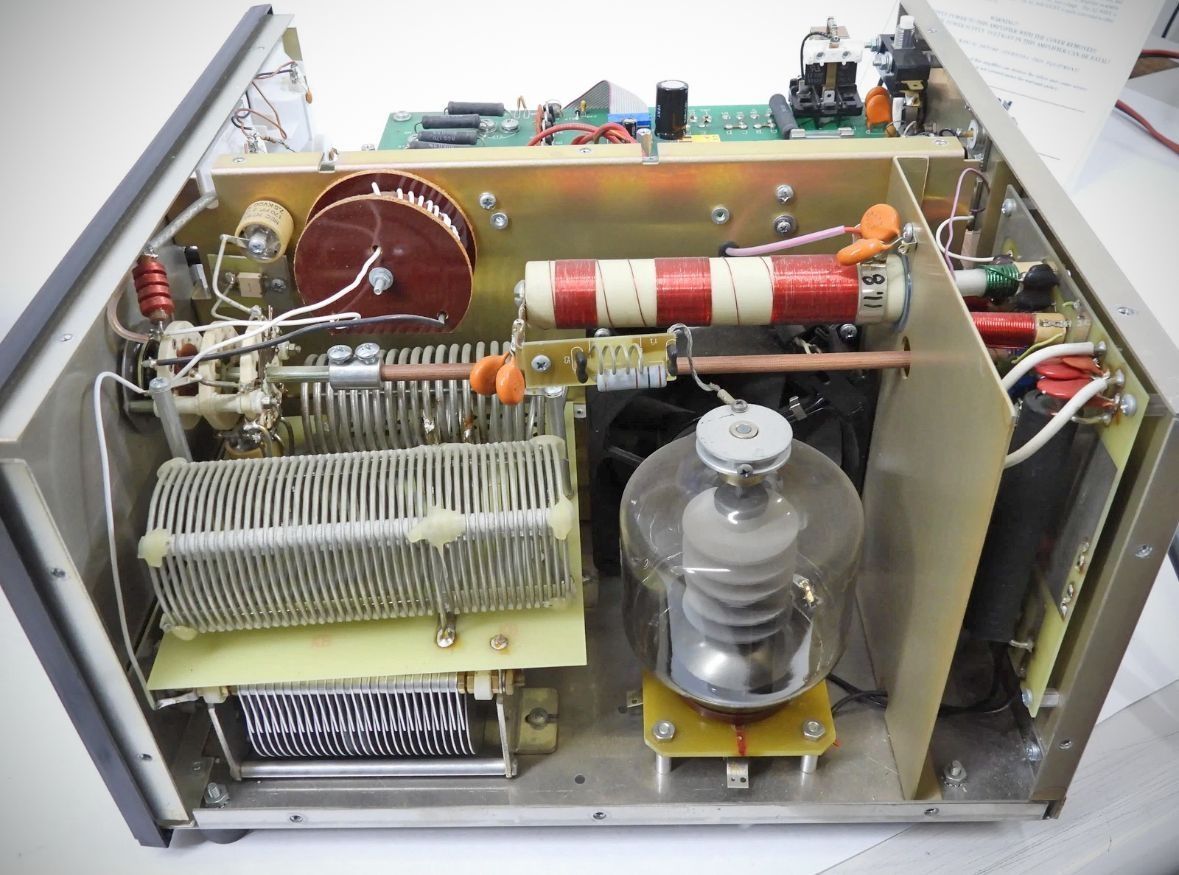
The AL-80B is a single-tube linear amplifier capable of delivering 1000 watts PEP SSB and 800 watts CW continuous output. It uses a single, rugged 3-500Z triode tube configured in a class $\text{AB}_2$ grounded-grid circuit. The standard domestic model covers the amateur bands from 160 through 15 meters, while export variants (AL-80BX and AL-80BY) also include coverage for 10 and 12 meters.
The Ameritron AL-80B represents a comprehensive redesign and modernization of the older AL-80A. While both amplifiers are built around a single 3-500Z triode tube, the AL-80B (developed after MFJ’s acquisition of Ameritron) introduced several circuit, metering, and hardware upgrades designed to improve efficiency, heat management, and usability.
The key differences between the AL-80A and the AL-80B include:
1. Advanced Bias Control & Heat Reduction
AL-80A: Employs a basic, static Zener diode arrangement for cathode bias. The tube draws a constant quiescent (idling) current whenever the amplifier is keyed, generating continuous heat even during pauses in speech or code.
AL-80B: Features an exclusive Instantaneous RF / Dynamic Bias Circuit. It samples the incoming RF drive voltage to actively control the operating bias. Between words on SSB or between dots and dashes on CW, it drops the idling current close to the tube's cut-off point. This eliminates hundreds of watts of wasted standby heat, resulting in much cooler overall operation and longer component life.
2. High-Level RF Processing (Dynamic ALC)
AL-80A: Uses a traditional, passive ALC layout designed mainly to prevent the transceiver from overdriving the amplifier and flat-topping the signal.
AL-80B: Upgraded to a user-adjustable Dynamic ALC Circuit with front-panel control (`ALC SET`) and rear-panel limits. When adjusted, it functions as a low-distortion, high-level RF speech processor that effectively doubles average SSB talk power (yielding up to a 6 dB improvement in signal intelligibility) without introducing splatter.
3. Upgraded Power Supply & Line Voltage Flexibility
AL-80A: Features primary transformer taps that offer limited line voltage adjustments (standard domestic configuration came factory-wired for 117 VAC and could be jumped to 234 VAC).
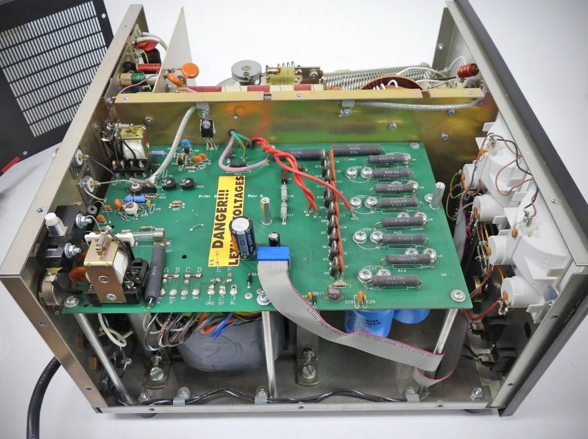
AL-80B: Equipped with a larger, heavier power supply using a 26-pound grain-oriented E-I lamination transformer. Its primary "buck-boost" winding configuration allows users to customize the amplifier to 14 different line voltage combinations centered around 115 and 230 VAC to precisely counter local line-voltage sag.
4. Metering System Evolution
AL-80A: Uses two individual, single-needle meters. The right meter is permanently dedicated to tracking grid current, while the left meter is a multimeter that switches between high voltage plate current), peak output power, and ALC.
AL-80B: Replaced the older layout with a modern dual cross-needle meter system. The left meter combines grid current and plate current simultaneously on intersecting scales, giving an instant visual representation of tube loading. The right meter utilizes a highly accurate peak-detecting directional coupler to continuously track peak forward power on one needle, while the second needle monitors reflected power/SWR, HV, or ALC.
Features
– Dynamic Bias Circuit: An exclusive feature that samples a small portion of the RF drive voltage to actively control the tube's operating bias. When no signal is present, it drops the quiescent (idling) current close to the tube's cut-off region. This eliminates hundreds of watts of unnecessary heat generation between words on SSB or dots and dashes on CW, leading to cooler operation and longer component life.
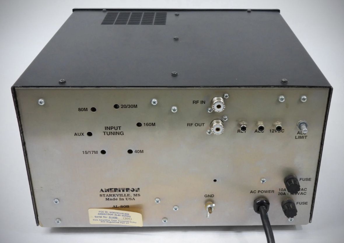
– True ALC Circuit: Unlike basic configurations, the AL-80B employs a "true" automatic level control that samples grid current and power supply loading. A front-panel "ALC SET" control allows the user to adjust the threshold where ALC action begins. It starts softly over a range of a few milliamperes to limit distortion and flat-topping. Additionally, a rear-panel "ALC LIMIT" control sets the maximum negative voltage (0 to 10 volts) available to eliminate overshoot or signal "motor-boating" caused by transceiver delay.
– Multi-Voltage Power Transformer: Features a "buck-boost" primary winding layout that allows users to adjust the transformer configuration to accommodate 14 different line voltages centered around 115 and 230 VAC. This allows optimization for local line drop or variations.
– Step-Start System: A 10-ohm resistor limits the initial inrush current during the filter capacitor charge time to decrease stress on the power supply components and the tube filament. Once the charging current drops sufficiently, an internal relay (RLY102) shorts out the resistor to apply full line voltage.
– Power Supply: Full-wave voltage doubler circuit utilizing 200-amp surge-rated diodes and a 26-pound E-I lamination grain-oriented transformer. Filter capacitance totals 26 $\mu\text{F}$ using computer-grade capacitors, with large 50k ohm, 7-watt bleeder resistors for safe voltage equalization.
Specifications
– Input Circuit type: Pi-network, slug tuned coils
– Maximum VSWR at resonance: 1.3:1 or less
– Minimum 2:1 VSWR bandwidth: 20% of center frequency
– Maximum drive power permissible: 100 watts PEP
– Typical drive for full power output: 85 watts
– Output Circuit type: Pi-L, Pi-network
– Typical SSB PEP voice operation: 1000+ watts
– CW continuous operation: 800 watts
– 1/2 hour PEP two-tone test: 850 watts
– 1/2 hour continuous carrier (RTTY): 500 watts
– Frequency Coverage: 1.8 to 21 MHz amateur bands. (Export models include 24.5 and 28 MHz)
– Third Order IMD: -35 dB or better (at rated output)
– Efficiency:
CW: approximately 65%
SSB: approximately 65% (envelope crest)
– Power Supply: Circuit type: Full wave voltage doubler
No load voltage: 3100 V
Full load voltage: 2700 V
Full load current: 0.6 A
Regulation: >13%
Transformer: 26 lb. E-I lamination grain oriented
Capacitors: 26 mFd total, computer grade
– Normal line current at rated CW output: 12 A at 120 Vac
– Normal line current at 1000 watt PEP output: 8 A at 120 Vac
– Power line current in standby: 1 A at 120 Vac
– Tube: Type: 3-500Z
– Continuous dissipation: 500 watts
– Warm-up time: 10 seconds
– Estimated life: 12,000 hours ICAS
– ALC: Negative going, 0 to 10 volts, adjustable.
– Relay: Requires contact closure or sink of +12 Vdc at 100 mA. Back pulse protected.