Note
QST, Aug 1955, p. 129.
Allied Radio catalog 1956 (copyright 1955), p. 200.
Allied Radio catalog 1957 (issued 1956), p. 248. (380B)
CQ, Dec 1967, p. 48. (this could be an error)
Walter Ashe catalog 1957 (probably issued in 1956), p. 3.
Allied Radio catalog 1959 (issued 1958), p. 379.
Allied Radio catalog 1960 (copyright 1959), p. 403.
Allied Radio catalog 1961 (copyright 1960), p. 399.
CQ, Feb 1963, p. 98. (381B)
QST, Apr 1963, p. 140
CQ, Feb 1964, p. 40.
The following is a description of the 381B.
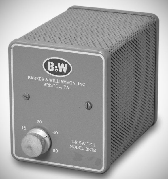
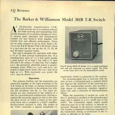
The Barker & Williamson (B&W) Model 381B is a self-powered, all-electronic transmit-receive (T-R) switch designed for amateur radio operation across the 10, 15, 20, 40, and 80-meter bands. It enables a single antenna to be shared between a transmitter and a receiver without requiring a mechanical antenna changeover relay.
The antenna and transmitter connect directly at the input terminals. Incoming signals during reception feed into the cathode of a 6S4 vacuum tube operating in a grounded-grid configuration.
Unlike untuned broadband T-R switches, the 381B features bandswitched, tuned plate circuitry that couples into a 6AG5 pentode amplifier stage, which drives a broadband RF output transformer connected to the receiver. The internal bandswitch coils are arranged in a ring layout around the selector mechanism.
When transmitting, RF potential is rectified inside the grounded-grid stage to develop a negative DC cutoff bias. This bias is applied to the 6AG5 pentode, attenuating the transmitted signal to safe levels to protect the receiver front-end. Protection operates automatically across all bands regardless of the bandswitch position.
Impedance & Power Ratings: Designed for 52-ohm or 72-ohm coaxial feedlines. At a 1:1 SWR, it is rated to handle peak power up to 5 kW on 52-ohm lines and 3 kW on 72-ohm lines. At legal power limits (CW, SSB, DSB), it can tolerate an SWR up to 4:1, or up to nearly 2:1 on AM.
Because of the tuned dual-tube architecture, the unit provides substantial RF gain rather than signal loss. Gain measures 8 dB on 10 meters, 14 dB on 15 meters, 19 dB on 20 meters, 18 dB on 40 meters, and 14 dB on 80 meters. Average sensitivity is 0.5 µV for a 10 dB S/N ratio on AM and 0.5 µV for a 20 dB S/N ratio on CW/SSB.
Noise Figure: 6 to 7 dB on 28 MHz.
Front Panel: Contains a single control knob for selecting the 80, 40, 20, 15, or 10-meter bands.
Rear Panel: Features three SO-239 coaxial chassis connectors labeled for the Antenna, Transmitter, and Receiver, along with the AC power cord entry.
Extension Shaft: The rear end of the bandswitch shaft extends out through the back panel, allowing it to be mechanically coupled to external switching systems, such as auxiliary relays for band-specific antenna switching.
Power Supply: Houses an internal AC power supply designed for 117V AC operation. It lacks an independent power switch; B&W recommends wiring its power cord to the receiver's primary power circuit so it turns on and off with the receiver.
References
Brief description. Radio News, Mar 1959, p. 142.
Review (381B): CQ, Feb 1964, p. 40.