Note
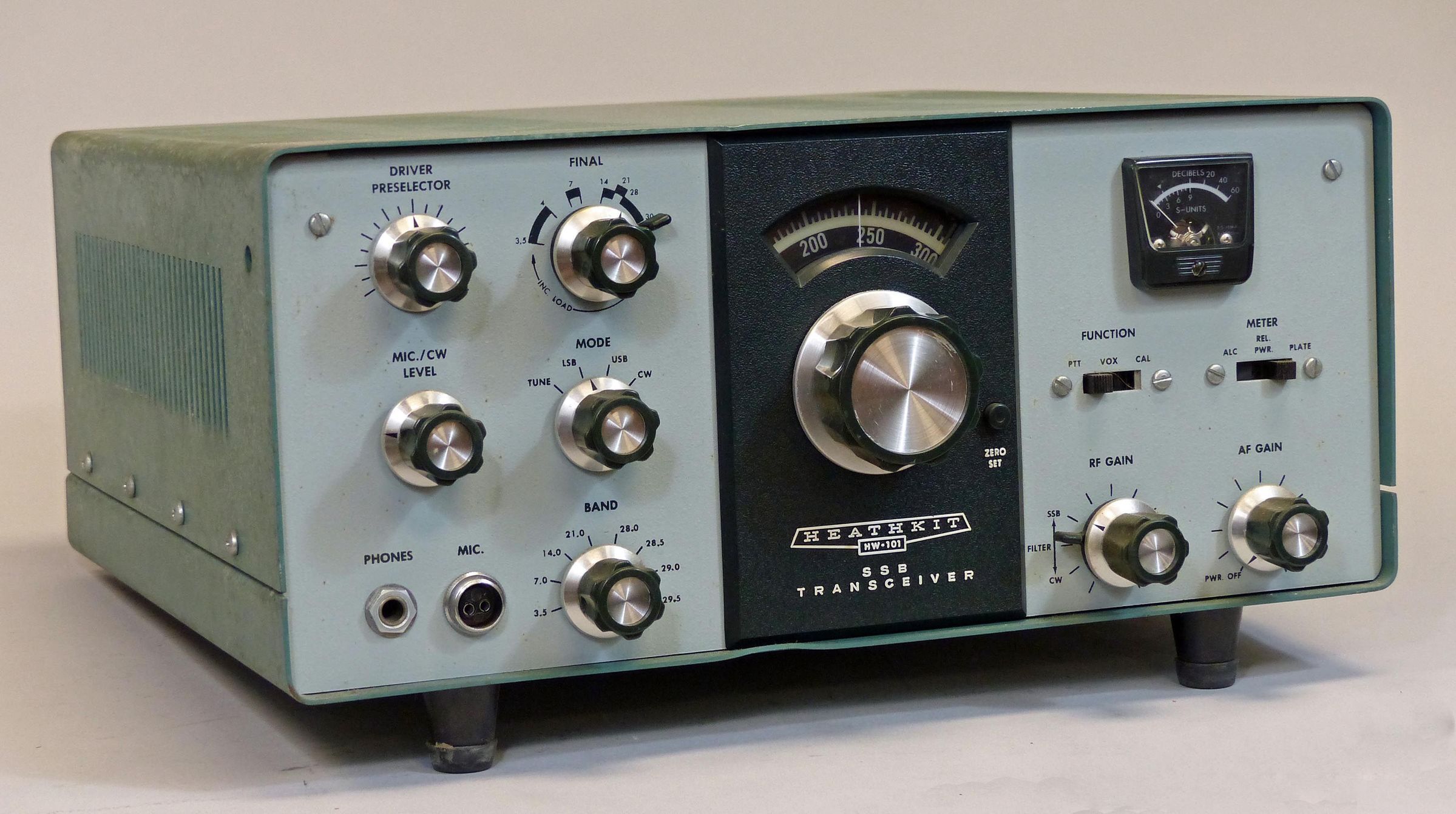
Released for Christmas in 1970, the HW-101 was a refinement of the HW-100 and proved to be even more successful. When the last ad for the 101 appeared in the Winter 1983 catalog, Heath noted that more than 30,000 units had been sold. It is likely that the final number was closer to 40,000. This is a truly staggering number of radios, and it is doubtful that that figure will ever be equaled by any other manufacturer for any kind of transceiver.
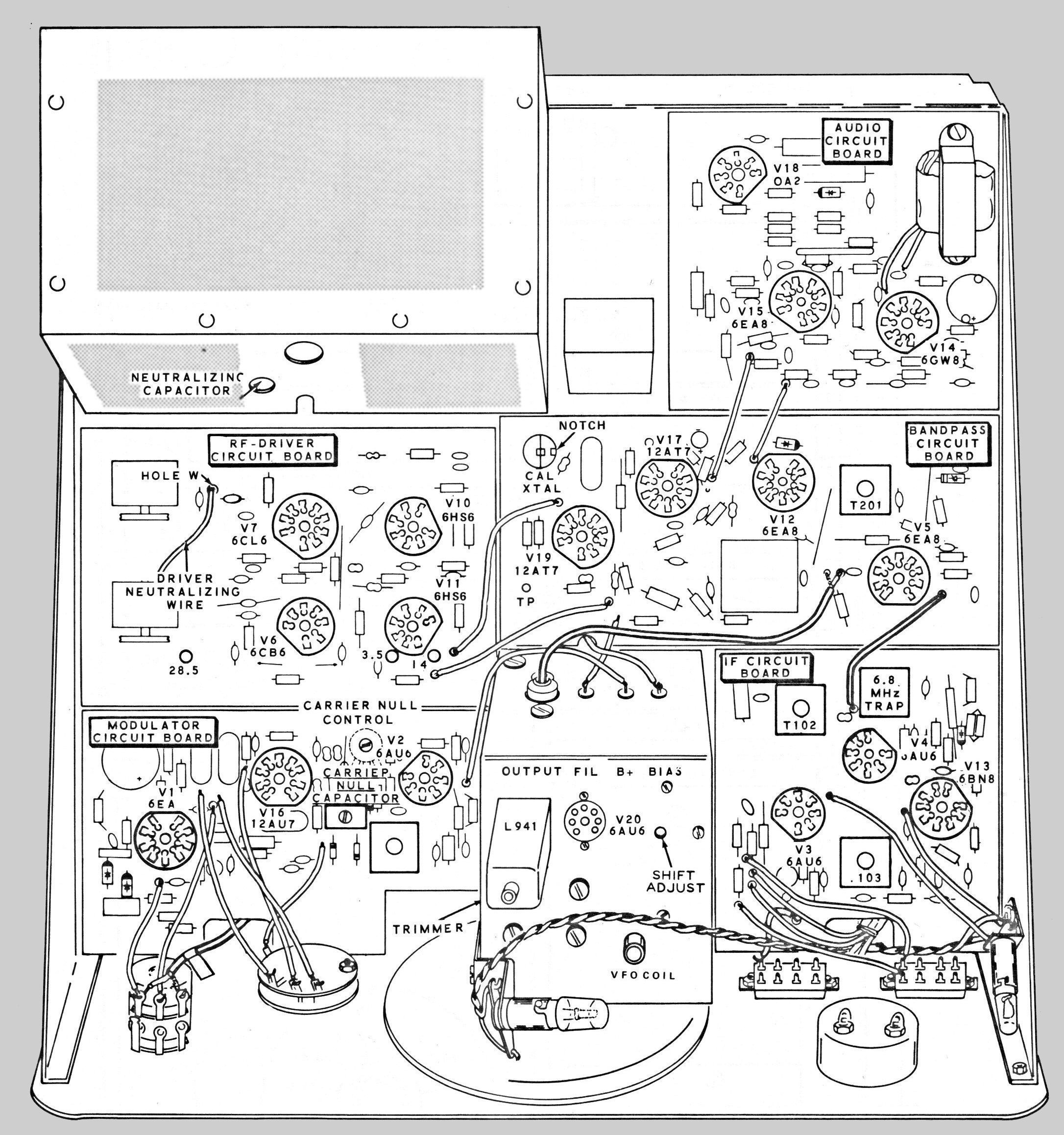
There are three primary improvements in the HW-101. First, the receiver sensitivity has been improved and is now better than 0.35 µV (as opposed to 1.0 µV in the HW-100). This increase was accomplished largely by replacing the 6AU6 tubes at V10 and V11 (on the RF drive circuit board) with type 6HS6 tubes.
Secondly, the Harmonic Drive tuning mechanism no one seemed to like was replaced with a more conventional ball bearing drive with a 34:1 tuning ratio (as opposed to the 28:1 in the HW-100).
Lastly, Heath added front panel switch selection of filters for SSB and CW (the HW-100 has only an SSB filter), though the 400 Hz CW filter was optional. The enclosure must be removed to check for the presence of the CW filter. See listing for SB-101 for details on checking for the CW filter.
One other small improvement Heath made was to fix the problem with the driver preselector found in the SB-100, SB-101, certain SB-102s, and the HW-100.
The HW-101 uses Heath’s triple-action-level control (TALC) to prevent overdriving of the final amplifier.
To better distinguish the 101 from its predecessor, Heath restyled the transceiver's front panel. All other operating characteristics of the HW-101 are the same as the HW-100. The HW-101 was the last tube-type rig Heath ever made and is the most popular radio it ever sold. It is a true classic, and hundreds are still on the air. Look for the two-tone green cabinet and SB series knobs. Beware strange modifications.
Note: Uses the not-quite-as-sharp 404-328 crystal filter. Type 404-283 is a bit sharper and was supplied with the SB-101. See SB-100 for a discussion of available crystal filters.
Note: use only 6146 finals. The use of 6146A, 6146B or 6146W types can be problematic in operation.
See HW-100 for additional discussion.
References:
Review. QST. Jan 1972, p. 59.
RIT. QST. May 1967, p. 49.
RIT. Ham Radio. Jun 1969, p. 67.
RIT. CQ. Jul 1969, p. 86.
RIT. QST. Oct 1974, p. 38.
RIT. Ham Radio. Aug 1976, p. 81.
WWV reception. QST. Apr 1969, p. 47.
WWV reception. QST. Aug 1977, p. 49.
WWV reception. Ham Radio. Jan 1977, p. 78.
Better connection to SB-620. CQ. Feb 1970, p. 89.
Adding a 400 Hz filter. QST. Nov 1971, p. 20.
Sidetone gain control. CQ. Apr 1972, p. 12.
Increasing capabilities of. CQ. Aug 1972, p. 16.
Tone oscillator repair. QST. Sep 1972, p. 53.
Sidetone gain control. CQ. Jan 1973, p. 90.
Grid current monitor. Ham Radio. Feb 1973, p. 46.
Use with a separate receiver. Ham Radio, Oct 1973, p. 63.
Offset tuning and keying mods. QST. Mar 1975, p. 19.
Offset tuning and keying mods (more on). QST. Aug 1975, p. 49.
A receiver pre-amp for. CQ. Mar 1976, p. 26.
Improvements. CQ. Mar 1976, p. 43.
VFO slippage and backlash. QST. Sep 1976, p. 39.
Digital display for. Ham Radio. Sep 1976, p. 16
VOX relay response in CW operation. QST. Jan 1977, p. 44.
Better looking dial. QST. Feb 1977, p. 43.
Underrated resistor / CW desense. Ham Radio. Mar 1977, p. 79.
Heterodyne crystal switching. Ham Radio. Mar 1977, p. 78.
WWV mod. QST. Aug 1977, p. 49.
WWV mod (correction). QST. Sep 1977, p. 51.
Use with low impedance headphones. Ham Radio. Oct 1977, p. 87.
CW modification. QST. Mar 1978, p. 41.
Holding the relay. QST. Apr 1979, p. 44.
Sidetone volume control. Ham Radio. Jul 1979, p. 79.
Eliminating TVI. QST. Aug 1979, p. 50.
Modification for zero-beating. QST. Feb 1981, p. 47.
Sidetone volume reduction. QST. Jun 1981, p. 36.
Mic preamp using V5B. 73 Amateur Radio. Oct 1981, p. 52.
Fixing speaker thump. QST. Feb 1982, p. 50.
Loading cap protection. QST. Feb 1982, p. 50.
Improved carrier suppression. QST. Oct 1982, p. 43.
Troubleshooting chart. QST. Feb 1983, p. 54.
Modification for 30 meters. CQ. Feb 1983, p. 31.
Oscillation problem. QST. Mar 1983, p. 42.
Modification. CQ. Mar 1984, p. 22.
Remote VFO using a salvaged LMO. 73 Amateur Radio. Aug 1984, p. 46.
Change CW offset. 73 Amateur Radio. Mar 1985, p. 48.
Digital frequency display, Ham Radio. Jan 1987, p. 8.
Drive dial slippage fix. QST. Mar 1988, p. 41.
Use with W6OWP keying interface. QST. Nov 1990, p. 38.
Optimizing. QST. Feb 2003, p. 77.
Review. Electric Radio. Jul 2006.
General information. Electric Radio. Nov 2006.
Rebuilding from scratch, Electric Radio. Jan 2019.
Band coverage: 80, 40, 20 , 15 and 10 meters
Frequency stability: less than 100 Hz per hour drift after 45 minutes warmup, less than 100 Hz for ±10% line voltage variation
Modes: USB, LSB, and CW
Dial calibration: 5 kHz divisions
Calibrator: 100 kHz
Bandspread: 35.33 revolutions for 500 kHz
Audio frequency response: 350 Hz to 2450 Hz
Sensitivity: less than 0.3 µV for 10 db signal-plus-noise to noise ratio (SSB)
SSB selectivity: 2.1 kHz minimum @ 6 db down, 7 kHz minimum @ 60 db down
CW selectivity (with optional SBA-301-2 filter): 400 Hz minimum @ 6 db down, 2.0 kHz maximum @ 60 db down
Audio power output: 2 watts with less than 10% distortion
Spurious response: image and IF rejection better than 50 db
DC power input:
SSB (A3J emission): 180 watts PEP (continuous duty)
CW (A1 emission): 170 watts (50% duty cycle)
RF power output: 100 watts on 80 through 15 meters, 80 watts on 10 meters
Output impedance: 50Ω to 75Ω with less than 2:1 SWR
Oscillator feedthrough or mixer products: 55 db below rated output
Harmonic radiation: 40 db below rated output
T/R operation:
SSB: PTT or VOX
CW: provide by operating VOX from a keyed tone, grid block keying
CW sidetone: approximately 1000 Hz
Microphone requirements: high impedance with ratings of –45 to –55 db
Carrier suppression: 45 db down from single-tone output
Unwanted sideband suppression: 45 db down from single-tone output @ 1000 Hz
Emissions not possible or not recommended: A0, A2, A3b, A4 through A9, F0 through F9, and P0 through P9
Third order distortion: 30 db down from two-tone output
RF compression: 10 db or greater @ 0.1 mA grid current
Power requirements:
700 to 850 VDC, 250 mA with 1.0% maximum ripple
300 VDC, 150 mA with 0.05% maximum ripple
–115 VDC, 10 mA with 0.5% maximum ripple*
12 VDC or VAC, 4.76 amps
Tubes: (1) 0A2, (2) 6HS6, (4) 6AU6A, (1) 6BN8, (1) 6CB6A, (1) 6CL6, (4) 6EA8, (1) 6GW8, (2) 12AT7, (1) 12AU7, (2) 6146
Solid State:
diodes: (2) 1N191, (4) 1N2071, (1) 1N4166A, (1) FH1100, (1) 1N2071, (1) 1N4149
transistors: (1) MPF105, (1) 2N3393
Photos, general information and specifications from "Heathkit: A Guide to the Amateur Radio Products," by Chuck Penson, WA7ZZE. Used with permission.