Note
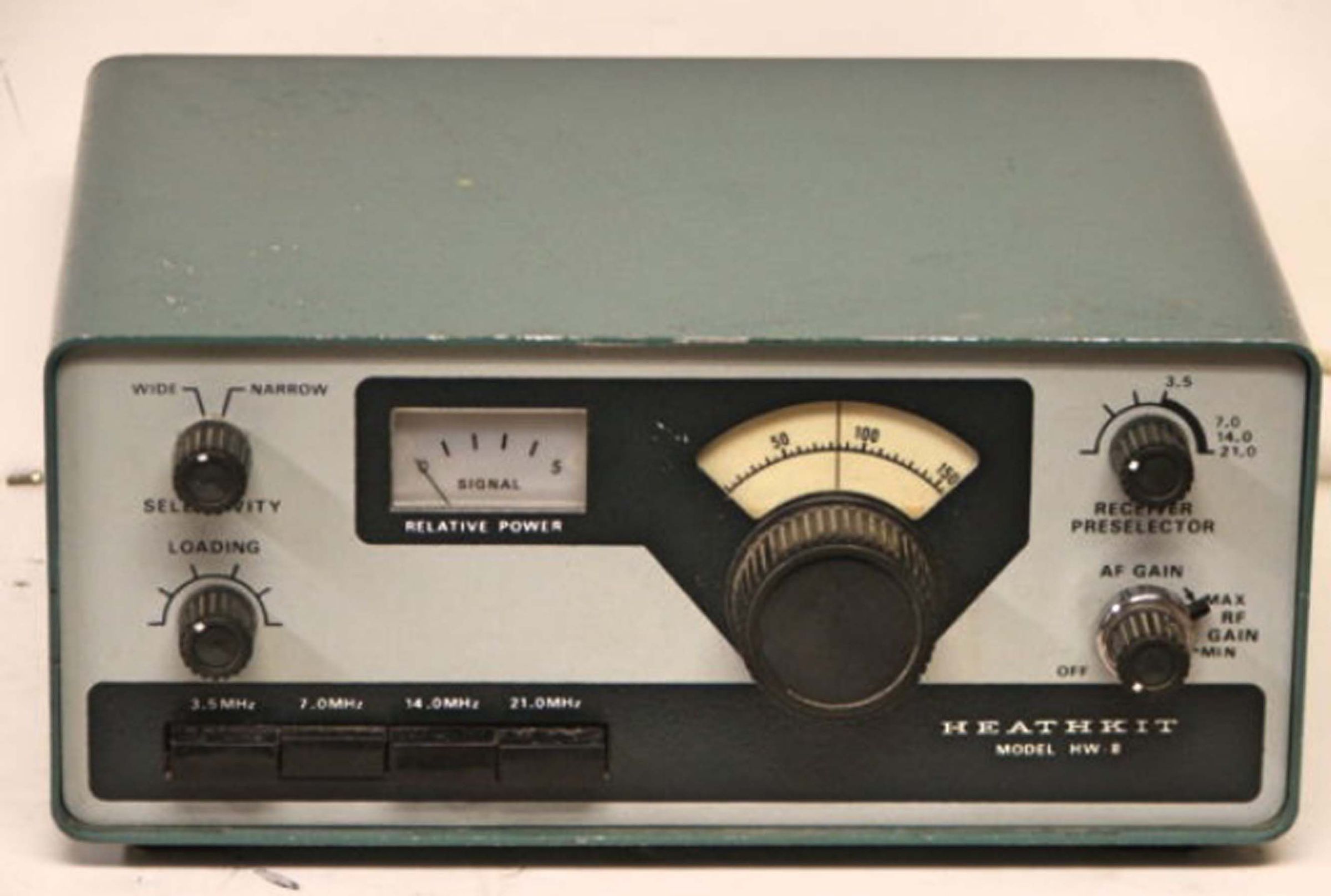
The HW-8 was far and away the most popular of the three versions of Heath’s QRP rigs and is still highly prized by those serious about QRP.
More than just an improved version of the HW-7, the HW-8 is a major overhaul with many added features. While a direct-conversion receiver is still used, Heath has added a JFET RF amp, a doubly balanced IC product detector, and an RC-active CW audio filter with two selectable bandwidths (wide—750 Hz and narrow—375 Hz). There is no internal speaker.
The receiver problems of the HW-7 (hum, microphonics, and cross-modulation) have been mostly fixed. In addition, Heath has added an RF gain control, adjustable sidetone volume, an S-meter, 80 meters, and wider frequency coverage on 40 and 20 meters. Note that no provision is made for crystal control. Sensitivity has also been improved to better than 0.2 µV. The minor transmitter chirp and click problems have been fixed as well.
Extensive use is made of diode switching in the low-level RF and DC sections. This helps maintain tuned-circuit Q, improves stability, and reduces spurious responses. Power output is about 2 watts on all bands.
A new crystal heterodyne circuit allows easier tuning with a single dial scale for all bands (6:1 tuning drive ratio). Like the HW-7, the HW-8 is not a QSK transceiver and has an adjustable delay T/R relay. Same two-tone green as HW-7 and other HW gear. Several books of modifications to the HW-8 have been published. One of the best is WB8VGE’s Hot Water Handbook.
References:
Review. QST. Apr 1976, p. 31.
Review. CQ. May 1977, p. 32.
Slippers (a small amp for). QST. Dec 1975, p. 45.
QSK and RIT. QST. Jul 1977, p. 22.
Contest Machine Part 1. CQ. Aug 1977, p. 48.
Contest Machine Part 2. CQ. Oct 1977, p. 62.
QSK and RIT (more on). QST Nov 1977, p. 20.
QSK and RIT (more on). QST. Jan 1978, p. 40.
QSK and RIT (more on). QST. Feb 1978, p. 27.
QSK and RIT (more on). QST. Dec 1978, p. 38.
Hum reduction, varactor diode replacement. QST. Mar 1978, p. 36.
25 kHz calibrator. QST. Oct 1978, p. 20.
“Boots” for. QST. Apr 1979, pp. 20, 47.
“Boots” for (correction). QST. Jun 1979, p. 18.
S-meter for. QST. Nov 1979, p. 57.
Ideas for. QST. Jan 1981, p. 45.
Modifications. QST. Jan 1981, p. 45.
Modification. CQ. Jan 1981, p. 48.
Use with “Accu-keyer”. QST. May 1981, p. 46.
Add speaker/amplifier. CQ. May 1981, p. 52.
Variable bandwidth for. QST. Apr 1982, p. 53
RIT for. CQ. May 1982, p. 98.
Band switch lights. CQ. Jun 1982, p. 46.
Improved keying. Ham Radio, Aug 1982, p. 60.
Modification. CQ. Oct 1982, p. 50.
Improved stability and dial calibration. Ham Radio. Nov 1982, p. 103.
30-meter modification. 73 Amateur Radio. Dec 1983, p. 52
Use on 30 meters. QST. May 1984, p. 44.
Frequency coverage: 3.5 to 3.75, 7.0 to 7.25, 14.0 to 14.25, 21.0 to 21.25
DC power input: 80m, 3.5 watts; 40m, 3.0 watts; 20m, 3.0 watts; 15m, 2.5 watts
Frequency control: VFO only
Output impedance: 50Ω unbalanced
Spurious and harmonic levels: at least 35 db down
Transmitter frequency offset: approximately 750 Hz lower, fixed
Sensitivity: better than 1.0 µV; 0.2 µV provides readable signal
Selectivity:
wide: 750 @ 6 db down
narrow: 375 Hz @ 6 db down
Passband center frequency: 750 Hz
Mode: CW only
Audio output impedance: 1000Ω nominal
Power requirements: 13.4 VDC nominal, 90 mA receive, 430 mA transmit
Solid State:
diodes: (24) 1N458, (8) 1N4149, (4) FH100, (1) VR36 zener, (1) VR9.1 zener
transistors: (1) X29A829, (1) MPF105, (1) S2091, (2) MPS6521, (6) MPSA20, (1) 40673, (1) 2N4427
integrated circuits: (1) LM3900, (1) MC1496
Photos, general information and specifications from "Heathkit: A Guide to the Amateur Radio Products," by Chuck Penson, WA7ZZE. Used with permission.