Note
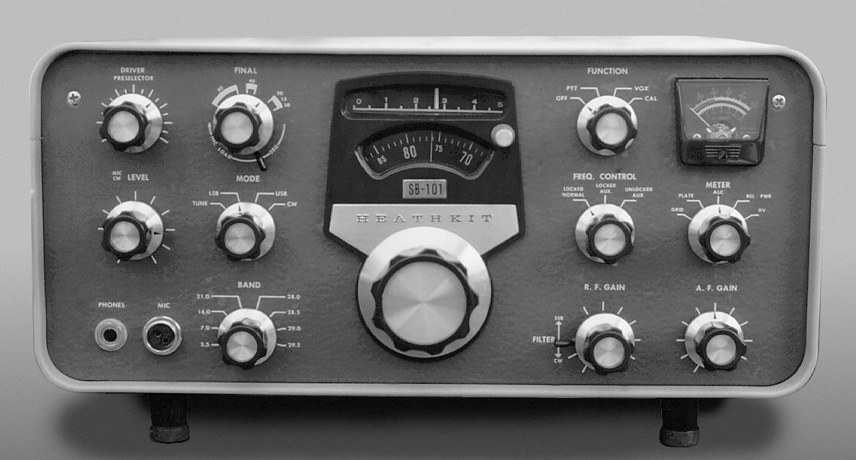
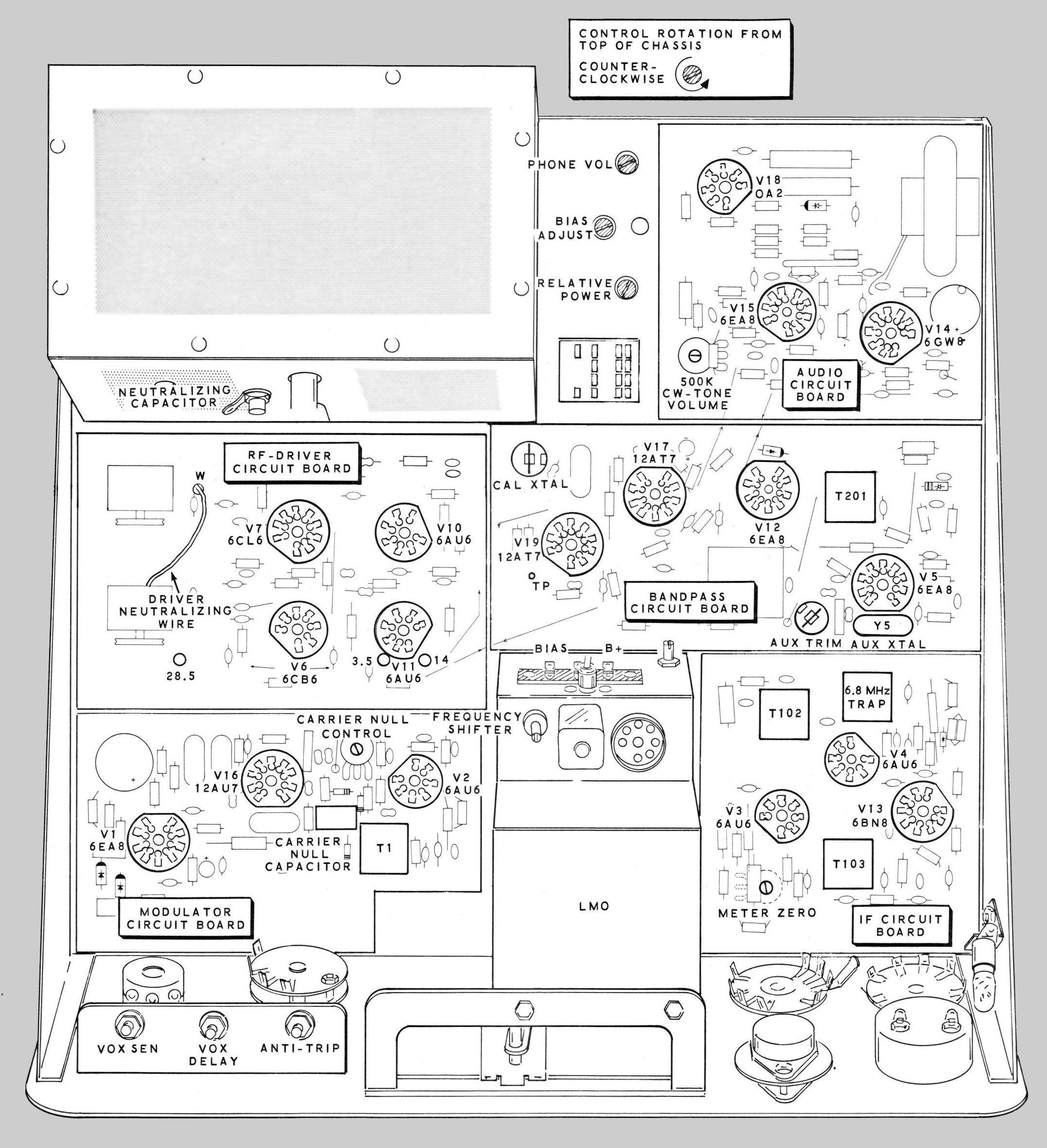
In 1967 Heath upgraded the popular SB-100 transceiver and renamed it the SB-101. There were two significant improvements in the SB-101. The first was the addition of a 400 Hz CW filter option. If this filter was installed the operator could select either the SSB or CW filter from a switch on the front panel. Heath advertised that the SB-101 was “the first transceiver on the market with front panel selection of SSB or CW filters.” The filter selector switch is a small lever switch located concentrically under the RF gain control. The presence of the CW filter can most easily be determined by removing the SB-101 from its enclosure. The SSB and CW filters are mounted on a metal bracket located on the underside of the chassis at the front of transceiver. Both filters are small black rectangular boxes about 2.5 inches wide and are installed side by side. If two boxes are seen, the CW filter is installed. The CW filter is usually clearly marked as being a 400 Hz unit.
The other improvement was a change in the frequency control switch permitting the use of an external LMO (VFO). This gave the operator independent control of the transmit and receive frequencies. Although the switch position is provided for, actual use of the remote LMO (SB-640) requires a modification of the transceiver. Among other things it requires the removal of a rectangular knock-out on the rear of the enclosure (above the ground post), the installation of a connector and its mounting bracket on the chassis just behind the knock-out, and some wiring changes. Inspection to determine the presence of the connector is the easiest way to see if the rig has been modified for use with the SB-640. Note: The modification for the SB-102 is slightly different. Refer to SB-102 and SB-640 for details.
A minor change to the SB-101 was deletion of the 600Ω audio output jack. This jack was changed to a spare, for a total of two spare jacks. These jacks can be used for connection of the SB-610 or SB-620. After the release of the SB-102, owners of the SB-101 were offered an upgrade kit (for a small charge). This up-grade kit addressed only one of the improvements found in the SB-102—receiver sensitivity. The kit amounted to a new RF amplifier tube (a 6HS6 to replace a 6AU6 at V10) and a couple of new parts. Checking for the presence of this mod is a bit tricky. All of the changes made are made to the component side of the RF driver circuit board. This board sits directly in front of the final amplifier cage. Look between tubes V10 and V11 (these are the tubes on the right-hand side of the board) for the addition of a resistor and a small disk capacitor that have been tack soldered between other existing parts. Also look for the space left by a disk capacitor clipped out near V10. These changes indicate that the mod has been done. Note that 6HS6 tubes are scare today and may have been replaced by a 6AU6. Also, note that much of the improvement achieved with this modification can be accomplished simply by changing to the new tube.
A modification must be made to accommodate use of the SB-640 remote LMO. See SB-640 for details.
References:
CW sidetone pitch mod. QST. Jun 1968, p. 38.
LMO FMing fix. QST. Oct 1968, p. 44.
Use with SB-640 and not lose XTAL control. QST. Oct 1968, p. 45.
Preselector improvement. QST. Nov 1968, p. 50.
Receiver offset tuning. QST. Mar 1969, p. 46.
WWV reception. QST. Apr 1969, p. 47.
WWV reception. Ham Radio. Jan 1977, p. 78.
Better connection to SB-620. CQ. Feb 1970, p. 89.
MARS operation with. CQ. Apr 1971, p. 72.
Use with 6146B. CQ. Apr 1971, p. 72.
Narrow shift RTTY reception. Ham Radio. Oct 1971, p 64.
Narrow shift RTTY reception. Ham Radio. Jun 1973, p 54.
Hum. QST. Jun 1971, p. 40.
Hum / hot resistor. Ham Radio. Jun 1975, p. 59.
Hum / relay mods. Ham Radio. Jun 1976, p. 34.
Hum. CQ. Nov 1969, p. 90.
Adding RIT. QST. May 1967, p. 49.
Adding RIT. Ham Radio. Aug 1976, p. 81.
Increasing capabilities of. CQ. Aug 1972, p. 16.
Increase friction in worn zero set. QST. Jan 1973, p. 52.
Use with a separate receiver. Jan 1975 QST, p. 44.
OSCAR reception. QST. Feb 1975, p. 46.
Speech processor. Ham Radio. Jun 1975, p. 38.
Hum reduction. QST. Aug 1976, p. 43.
Digital display for. Ham Radio. Sep 1976, p. 16.
Faster relay response. QST. Feb 1977, p. 43.
Perking up. QST. Feb 1977, p. 44.
Underrated resistor / CW desense. Ham Radio. Mar 1977, p. 79.
Heterodyne crystal switching. Ham Radio. Mar 1977, p. 78.
Use with low impedance headphones. Ham Radio. Oct 1977, p. 87.
Excessive CW recovery delay. Ham Radio. Mar 1978, p. 110.
Hints for owners / Peaking T1. QST. Sep 1977, p. 44.
S-meter problem. QST. Apr 1978, p. 40.
Better S/N and gain for. QST. Jun 1978, p. 44.
Zero-set dial modification. QST. Feb 1980, p. 44.
Low sensitivity and RF drive fix. QST. Dec 1980, p. 53.
Digital frequency display, Ham Radio. Jan 1987, p. 8
Optimizing. QST. Feb 2003, p. 77.
General information. Electric Radio. Nov 2006.
General information about SB series. Electric Radio. Sep 2016.
Tubes: (1) 0A2, (5) 6AU6, (1) 6BN8, (2) 6CB6, (1) 6CL6, (4) 6EA8, (1) 6GW8, (2) 12AT7, (1) 12AU7, (2) 6146
Photos, general information and specifications from "Heathkit: A Guide to the Amateur Radio Products," by Chuck Penson, WA7ZZE. Used with permission.