Note
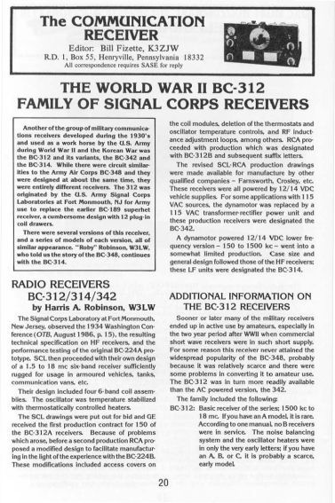
The BC-312 is a ruggedized military communications receiver originally developed during the 1930s by the U.S. Army Signal Corps Laboratories (SCL) at Fort Monmouth, New Jersey. Designed to replace the cumbersome BC-189 (which required 12 separate plug-in coil drawers), the BC-312 served as a dependable "workhorse" for the U.S. Army through both World War II and the Korean War.
While it shared some circuit similarities and a concurrent design timeline with the Army Air Corps BC-348, it was an entirely distinct receiver. The BC-312 was specifically engineered to be tough enough for operation inside tanks, armored vehicles, and communication vans.
Built to exceptionally high manufacturing tolerances, featuring both fast and slow tuning controls. The main dial incorporates a 45-division logging scale that can be further subdivided into 100 segments per division via the vernier control, ensuring high logging accuracy.
Technical Specifications & Circuit Architecture
The receiver is a six-band superheterodyne system with an intermediate frequency (IF) of 470 kc.
Tube Lineup: The standard tube configuration for the BC-312 includes the following 9 tubes:
– 1st RF Amplifier: VT-86 / 6K7
– 2nd RF Amplifier: VT-86 / 6K7
– Mixer: VT-87 / 6L7
– RF Oscillator: VT-65 / 6C5
– 1st IF Amplifier: VT-86 / 6K7
– 2nd IF Amplifier: VT-86 / 6K7
– 2nd Detector: VT-88 / 6R7
– CW Oscillator: VT-65 / 6C5
– Audio Output: VT-66 / 6F6
The basic BC-312 was designed to run on a vehicle's 12/14 VDC supply utilizing a removable, hot-swappable internal dynamotor.
Oscillator Alignment: On bands A, B, and C, the local oscillator operates 470 kHz above the incoming RF signal; on the remaining bands, it runs 470 kc below the RF signal.
Production Evolution and Variations
General Electric (GE) won the initial contract for the first 150 production units (the BC-312A). Following early production challenges, RCA introduced structural revisions to streamline manufacturing based on lessons learned from the BC-224B receiver.
These modifications included adding access covers to the coil modules, introducing RF inductance adjustment loops, and removing the complex, power-hungry oscillator thermostats. These revised drawings were standardized across later manufacturing runs by companies like Farnsworth and Crosley.
The BC-312 Family
The design architecture spawned several related models depending on the power source and frequency requirements:
> High-Frequency Models (1500 kHz to 18 MHz)
BC-312 (DC Powered): The basic high-frequency receiver of the series, powered by 12/14 VDC vehicle storage batteries via a removable internal dynamotor.
Early suffix letters (A, B, and C) are rare and featured an antenna noise-balancing network to minimize vehicle ignition noise, along with 25-watt thermostatically controlled oscillator compartment heaters maintained at 110º F.
Later variants designated with an "X" suffix (subsequent to the "G" model) were redesigned to operate on 24-28 VDC.
BC-342 (AC Powered): The 115 VAC line-powered equivalent of the BC-312. It replaced the internal dynamotor with an RA-20 transformer-rectifier power unit. Like its DC counterpart, only the very early production letters retained the internal oscillator heaters and noise-balancing circuits.
> Low-Frequency Models (150 to 1500 kHz)
BC-314 (DC Powered): A lower frequency variant that shared the same case size, physical weight, and general mechanical design as the HF units. It ran on 12/14 VDC vehicle supplies using a dynamotor. Unlike the high-frequency models, its local oscillator was designed to operate at exactly 92.5 kc above the RF signal across all of its bands.
BC-344 (AC Powered): The 115 VAC mains-powered version of the low-frequency BC-314 architecture.
Deployment
The BC-312 was typically deployed as a component of a larger tactical radio installation rather than a standalone unit.
SCR-245 Radio Set: Commonly fielded in vehicular configurations, pairing the BC-312 with a BC-223 transmitter, a PE-55 dynamotor, interconnected terminal/junction blocks, and a shared single whip antenna.
Low-Frequency Pairing: The low-frequency BC-314 variant was frequently paired with the BC-191 transmitter (the ground liaison equivalent to the Army Air Corps BC-375).