Note
QST, Aug 1966, p. 133.
QST, Jan 1967, p. 125. (Details)
QST, Jul 1969, p. 144. (LK-2000HD (heavy duty)
QST. Jul 1971, p. 147. ("new improved")
Ham Radio, Aug 1972, p. 91. (close out)
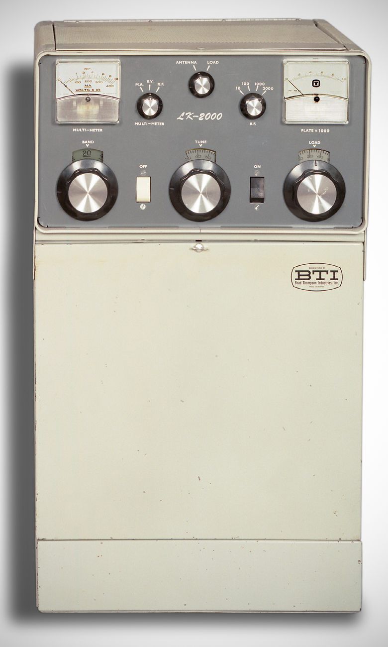
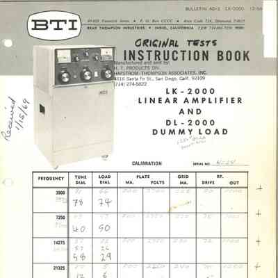
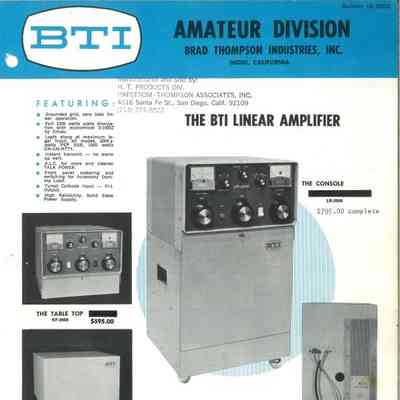
The LK-2000 from Brad Thompson Industries was designed for maximum legal input on all modes: 2000 watts PEP on SSB and 1000 watts on CW/AM/RTTY. The grounded-grid amplifier used a 3-1000Z tube and covered 80–10 meters. Its solid-state power supply operated from either 115 or 220 VAC.
Features
– Grounded Grid Linear Operation: Zero-bias linear operation.
– High-Power Tube: Uses an economical Eimac 3-1000Z tube providing a full 1000 watts of plate dissipation (also compatible with 4-1000A).
– Operating Power: Easily handles maximum legal input across all modes (2000+ watts PEP SSB, 1000 watts CW / AM / RTTY).
– Instant Transmit: No warm-up wait time required.
– Automatic Level Control (ALC): Features adjustable ALC feedback from the plate tank for cleaner talk power.
– Tuned Input & Output: Tuned Cathode Input with a Pi-L Output network.
– Metering & Switching: Front panel metering and switching for an accessory dummy load.
– Solid-State Power Supply: High-reliability continuous-duty power supply section.
– Silver-plated radio band switch deck and tank coil assembly.
Specifications
– Frequency Range: Covers amateur bands (and adjacent frequencies) from 3.5 MHz to 30 MHz.
– Drive Power: Requires 50 to 200 Watts RF drive
– Power Rating:
SSB: 2000+ Watts PEP
CW / AM / RTTY: 1000 Watts
Power Requirements: 115/230 VAC, 50/60 Hz, 20/10 amps.
Accessory Specifications (DL-2000 Dummy Load)
– Power Capacity: Handles input ratings up to 2000 watts to the final amplifier stage.
– Changeover Relay: Built-in relay switches transmitter output between antenna and dummy load (normally supplied with a 115 V AC coil).
– Thermal Protection: Includes a thermoswitch set to open if the load reaches 220º F.
– Enclosure & Dimensions: Long, narrow steel case with a perforated aluminum cover measuring 24 x 5.25 x 2.25 (must be operated vertically).
– Connectors: Two SO-239 coax connectors for input/output; control circuits carried via a 6-foot cable with a 6-prong Cinch-Jones connector.