Note
The HO-10 monitor scope was a brilliant idea. In one small box it combines everything needed to do all kinds of tests, adjustments, and measurements of your transmitter. It will display wave envelope patterns of AM, SSB, or CW signals; AM and RF trapezoidal patterns; and RTTY cross patterns. With the right connection to your receiver, it will also display patterns of received signals.
The HO-10 uses 5 tubes (excluding the CRT) and connects to the RF line with a pair of SO-239s in a simple loop-through configuration. A built-in tone generator provides single-tone or two-tone audio tests (1000/1700 Hz) at mic level—15 mV (peak).
The HO-10 requires a minimum of 5 watts of drive and will handle as much as 1000 watts. A rear panel attenuator control is used for adjusting the vertical deflection size based on your input power—0 to 24 dB in 6 dB steps.
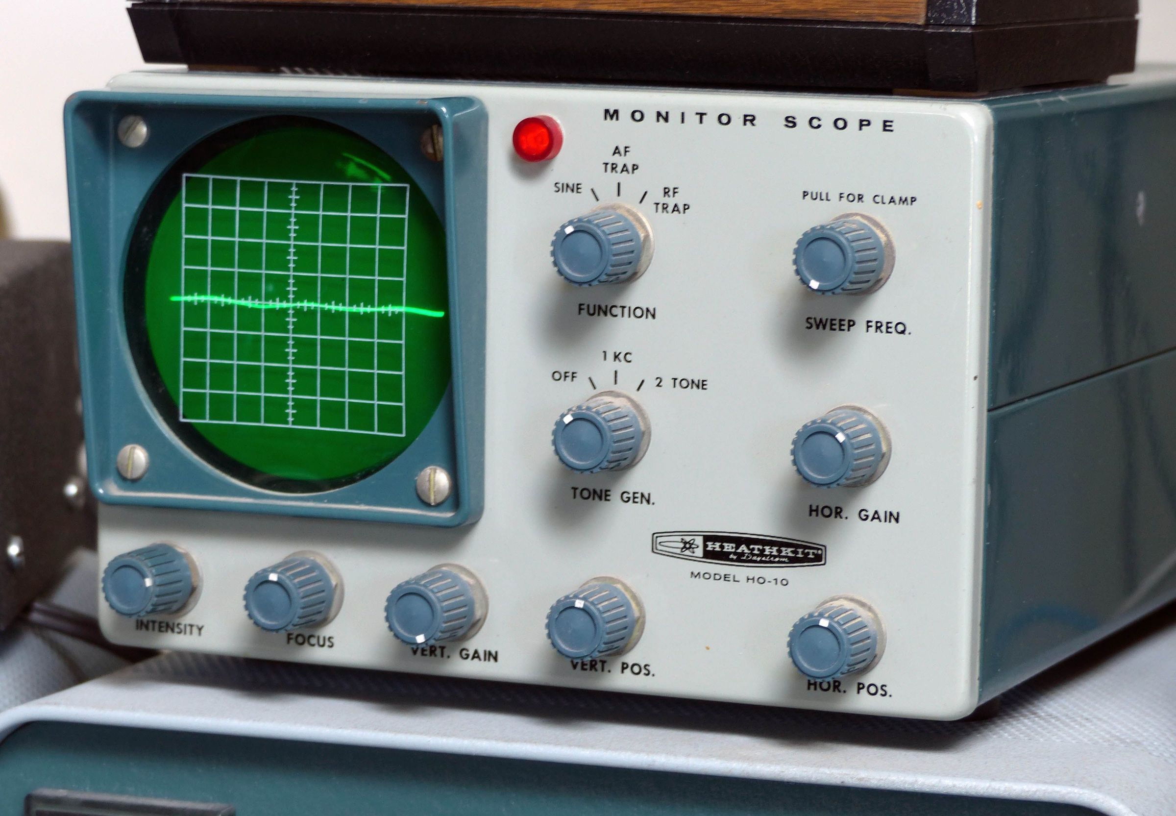
Front panel controls include intensity, focus, vertical and horizontal position and gain, sweep frequency (approx 10-200 Hz), tone generator, and function selector. In the AF and RF TRAP modes, a clamp circuit pulls the beam off the face of the tube when input signals are not present to prevent burning of the CRT.
Rear panel connections include loop-through SO-239s, loop-through RCA jacks for exciter input, vertical and horizontal RCA inputs for received signal and RTTY input, and an RCA jack output for the tone generator. (The 6J11 compactron tone generator is unrelated to the the rest of the circuit, and if it’s bad or missing, it will not affect the general operation of the scope.)
Vertical response is plus or minus 3 dB from 10 to 500 kHz with sensitivity of 500 mv per inch and an input resistance of 50kΩ. The horizontal section has a response of plus or minus 3 dB from 10 to 30 kHz with sensitivity of 800 mv per inch and an input resistance of 1MΩ.
Horizontal and vertical inputs on the rear panel permit the HO-10 to be used as a simple audio frequency oscilloscope.
With respect to monitoring received signals, the HO-10 is designed for use with receivers having an IF frequency of 500 kHz or less, and connects through a 5-15 pf capacitor to the grid (preferably) or plate circuit of the last IF stage of the receiver. It should be noted that any information gleaned about received signals monitored in this way is suspect at best since there are too many variables that can affect the quality of the incoming signal. Clearly, the monitoring of transmitted RF is the best use of the HO-10.
Using the HO-10 with a citizens band transceiver would require a modification of the scope to increase its vertical sensitivity. Such a modification is beyond the scope of this book, but is described in the assembly manual. Note: the mod involves a coil available only from Heath. The technically inclined person could figure out a work-around.
The HO-10 has a 50-75Ω coaxial input and a frequency coverage of 160-6 meters. The biggest problem with HO-10s seems to be the power transformer. It is a special design and if it goes out, your best option may be to find another HO-10 (or HO-13) for parts. Occasionally, HO-10s can be found without the power transformer, or with a home brew outboard power supply.
The HO-10 is almost indistinguishable from the matching HO-13. The cabinet is finished in a two-tone green, designed to match the TX-1, et al, and is fitted with a dark green bezel. The green reticule over the 3RP1 CRT is an 8 x 8 grid. In 1966 the HO-10 was refined, put into a cabinet that matched the new SB series and released as the SB-610.
Caution: Handle cathode ray tubes (CRTs) with great care.
Warning: Lethal voltages present when operating.
References:
Review. 73 Amateur Radio. Jul 1963, p. 78.
Review. QST. Dec 1963, p. 58.
Review. CQ. Jun 1964, p. 37.
Use for RTTY. Ham Radio. Sep 1974, p. 70.
Power transformer mod. Electric Radio. Nov 2003.
VERTICAL SECTION
Frequency response: ±3 db from 10 Hz ro 500 kHz
Sensitivity: 500 mV per inch of defection
Input impedance: 50kΩ
HORIZONTAL SECTION
Frequency response: ±3 db from 3 Hz ro 30 kHz
Sensitivity: 800 mV per inch of defection
Input impedance: 1MΩ
Sweep generator frequency: 15 to 200 Hz (variable)
GENERAL
Tone oscillator frequencies: approximately 1000 and 1700 Hz @ 15 mV nominal
Frequency coverage: 160 to 6 meters (50 to 75Ω coaxial input)
Power limits: 5 watts to 1000 watts
Transmitter attenuator: 0 to 24 db in 6 db steps
Power requirements: 102 VAC, 50/60 Hz, 35 watts
Tubes: (1) 6BN8, (1) 6C10, (1) 6J11, (1) 12AU7, (1) 1V2, (1) 3RP1 CRT.
Photos, general information and specifications from "Heathkit: A Guide to the Amateur Radio Products," by Chuck Penson, WA7ZZE. Used with permission.