Note
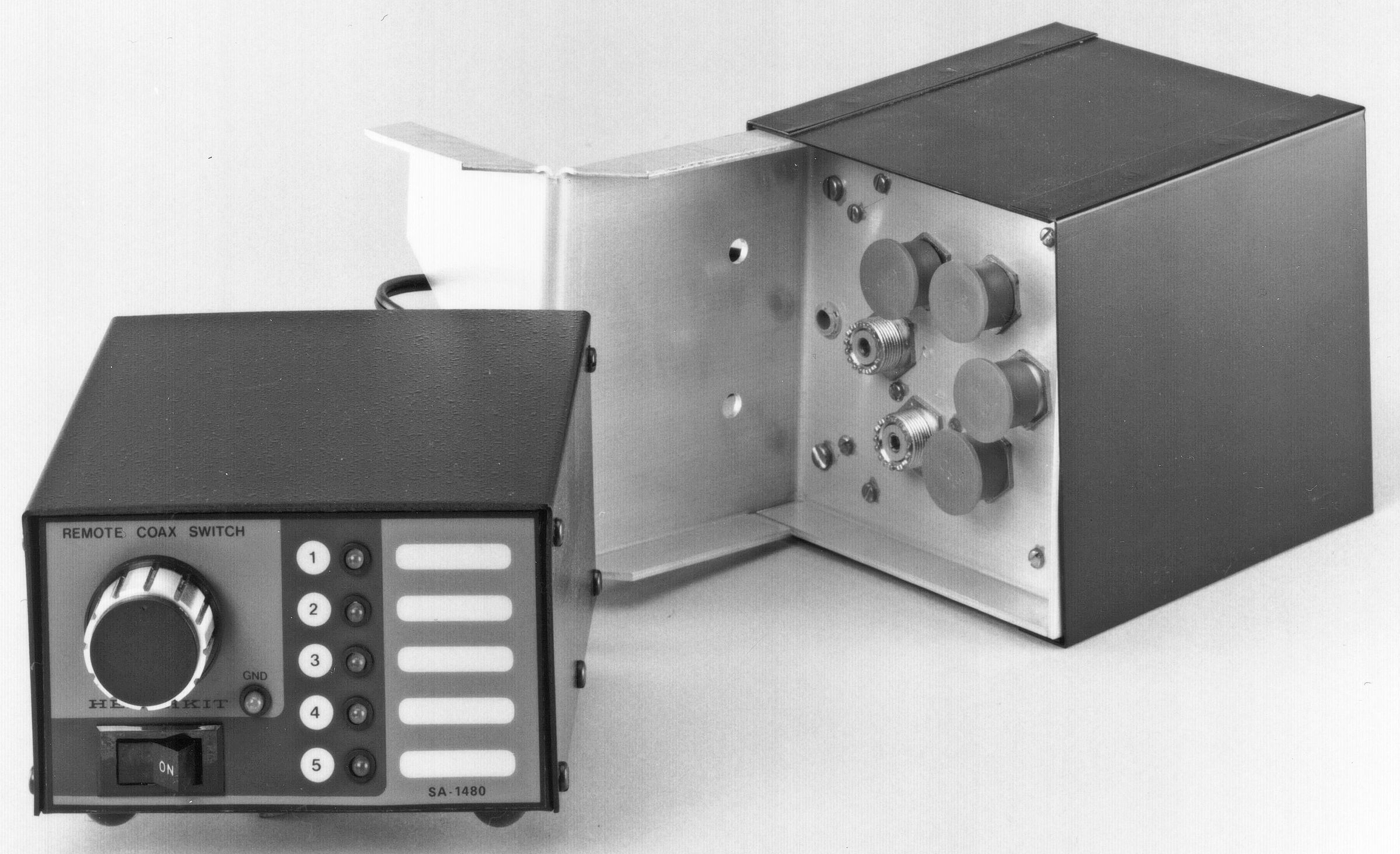
This was the first of two remote antenna switches made by Heath—and probably the better of the two units. The SA-1480 will remotely switch up to five antennas from a control box in your shack.
The actual switch box—typically tower mounted—is connected to the control box via a length of 8-conductor cable. A rotary switch on the control box activates a motor-driven switch in the remote unit to select which antenna will be placed on-line, and five LEDs show which antenna has been selected. Rotating the selector switch creates a circuit path on a rotating switch which then starts the motor. The motor then turns until an open circuit is found on the switch.
The 8-conductor cable may sound like a disadvantage compared to Heath’s later version, the HD-1481, which sent switching signals through the coax line, but the separate switching cable made the SA-1480 virtually bullet proof. It was immune from damage by high SWR, EMP, and so on.
Features include a special shielded, weatherproof switch housing and silver plated switch contacts. The only downside is that if the motor in the remote unit fails, it may be difficult to find a replacement.
In 1984 the SA-1480 was replaced by the HD-1481, but the two units were sold side by side for a short time. This is a well made unit and it is still in demand.
Caution: DO NOT rotate the sector knob to a different antenna position without first placing the POWER switch to ON. Doing so may stall the switching motor.
FOR USE WITH SS-9000
Without modification, the SA-1480 can be used with the SS-9000 transceiver, so that turning the band switch on the transceiver automatically operates the antenna switch. When so connected, the antenna switch can still be operated manually.
By connecting the appropriate wires from connector J1 (on the antenna switch motor housing of the transceiver) to the appropriate terminals on the SA-1480 control box, the correct antenna for the corrected band may be automatically selected. It is even possible to automatically select a tri-band beam. For automatic operation, the SA-1480 control box must be set to position 1. Note: An antenna connected to position 1 on the control box cannot be manually selected, but may still be selected automatically from the band switch of the transceiver. Figure 2 illustrates the basic idea for connection. Refer to SS-9000, page n-nn for additional details. The SS-9000 user manual provides full details.
References:
Review. QST. Jul 1980, p. 43.
Review. CQ. Oct 1980, p. 69.
TVI from. QST. Sep 1982, p. 42.
Increased control voltage for. QST. Jan 1983, p. 46.
Lubrication for sticky relays. QST. Mar 1983, p. 41.
Loss at 100 MHz: 0.2 db
VSWR:
Under 30 MHz: 1.05:1 or less
Under 150 MHz: 1.20:1 or less
Impedance: 50 to 70Ω
Power capability: 2000 watts PEP
Temperature range: –40 to +177 F
Number of ports: 5
Power requirements: 120/240 VAC, 50/60 Hz
Photos, general information and specifications from "Heathkit: A Guide to the Amateur Radio Products," by Chuck Penson, WA7ZZE. Used with permission.