Note
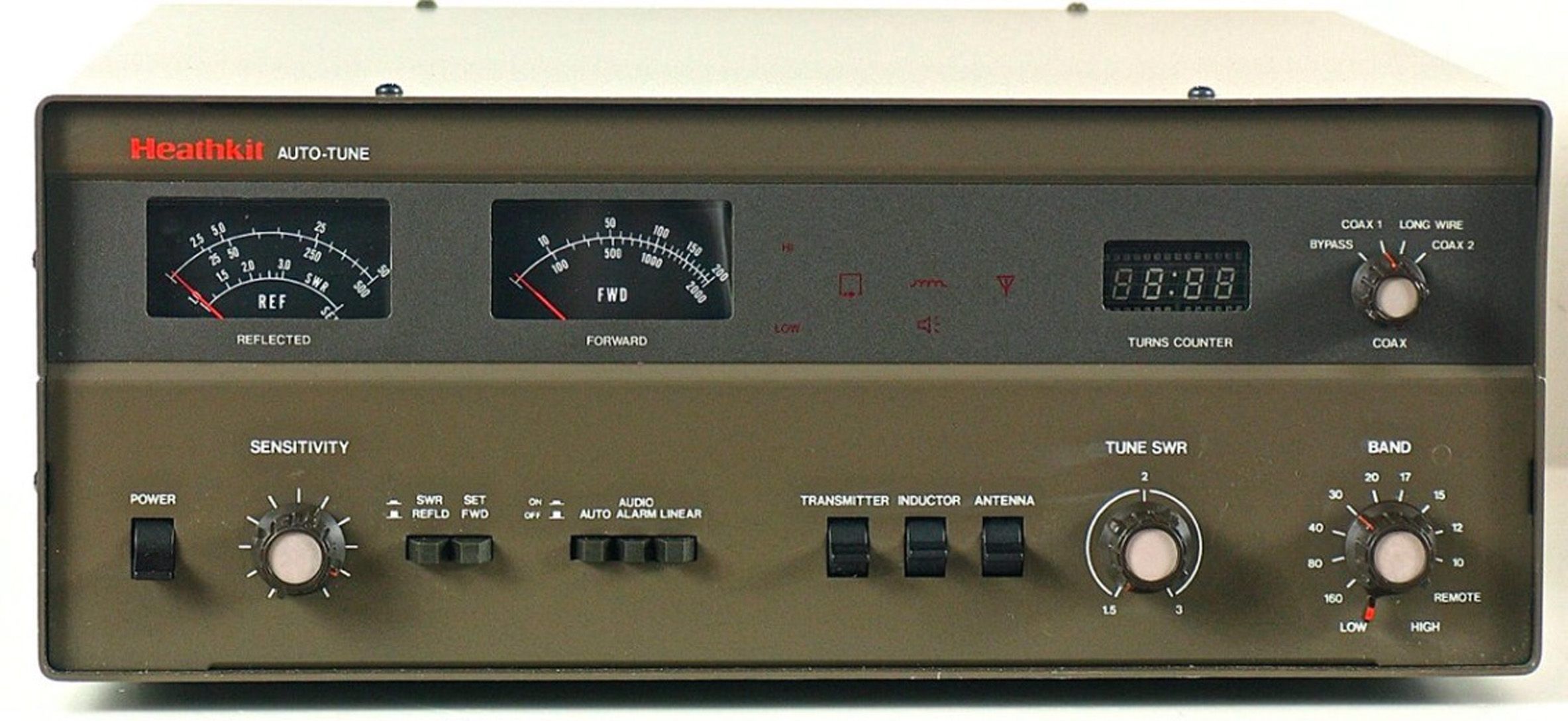
In the SA-2500, the capacitors and inductor are motor driven and controlled by an electronics package (on two PC boards) that senses minimum SWR. The unit will tune from 1.8 to 30 MHz and has an auto-ranging wattmeter and SWR bridge that reads from 0 to 200 or 0 to 2000 forward and 0-50 or 0-500 reflected.
Other features include an electronic digital readout turns counter and status light icons to indicate what elements of the tuner are being adjusted. There is also an SWR warning icon that flashes a light (and also sounds an alarm) to indicate when the tuned SWR exceeds a user preset level.
A front panel switch selects between three antennas and a bypass position (for use with a dummy load or resonant antenna, for example). Manual operation of the tuner is possible with three spring-return lever switches—one for each element in the tuner.
Because the roller on the inductor takes about a 90 seconds to make the trip from one end to the other, a total 18 preset positions are provided to speed the tuning process. This amounts to two per band, but any number of the presets (up to a total of 18) can be divided among any number of bands to best suit the user’s requirements. All 18 could be used on just two bands, for example. These preset positions are user selectable and can be reconfigured at any time.
Front panel controls include power on/off, SWR sensitivity adjust, SWR forward/reverse, auto/manual tune, SWR alarm on/off, linear amp on-line/off-line, and manual tuning controls. There are also controls for band, band high/low preset select, and antenna select.
Rear panel connections include an SO-239 input connector and three SO-239 outputs (coax 1, 2, and bypass). Standoff feed-throughs are used with a random wire and balanced lines (if the balun is installed). Other rear panel connectors include 12 VDC power, antenna relay (to disable your linear when tuning), and remote band switching (if your transmitter supports it).
Caution: The box on the rear panel containing the SO-239 connectors houses the power and SWR sensor circuits. This assembly was preassembled and adjusted. Tamper with it at your peril.
Automatic tuning time is about 15 seconds. The auto-tuning system requires a minimum of 35 watts input for proper SWR set.
The SA-2500 is two-tone brown in color to match the SS-9000. The unit works very well, but sales were held down because of the $600 price tag.
OPERATING NOTES
* In the AUTO mode, the roller inductor will return to the selected preset condition whenever the band switch or LOW/HIGH switch is changed.
* On initial turn-on, the two matching capacitors will rotate to the half-meshed position, and, if in AUTO mode, the roller inductor will return to the present condition.
* In the AUTO mode, the two variable capacitors rotate to the half-meshed position whenever the roller inductor starts turning.
* In some cases, when the tuner is in the AUTO mode, it will not be able to find a match. This may happen if the antenna’s impedance is outside the range of the tuner, or if the tuning components are very critical.
* If you want a better match than can be found in AUTO mode, place the tuner in MANUAL mode and use the lever switches to adjust one or both capacitors, as necessary.
* The tuner will, if possible, tune for a match with an SWR below the setting of the TUNE SWR control. If a match with the preset SWR cannot be found in 20 seconds, the alarm indicator will flash. An audible alarm will also sound, if selected.
* The alarm circuits may be activated under the following conditions:
* Upon initial power turn-on.
* When the SWR as seen by the tuner exceeds the setting on the TUNE SWR control.
* Tune time exceeds 15 to 20 seconds.
* When you are making measurements to determine the SWR.
* The tuner will not operate in the AUTO mode if either the SWR or SET switches are placed in the IN position.
* If the SWR of the antenna exceeds the setting of the SWR TUNE control for any reason (change of operating frequency, for example), an alarm will flash (and sound). The tuner will attempt to return to the new conditions, if in the AUTO mode.
* In the AUTO mode, it is normal for the tuner to retune if the SWR changes as you apply more power to the antenna.
REMOTE BAND SWITCHING / SS-9000
Remote band selection is accomplished by grounding the appropriate pin of the 9-pin rear panel connector. Front panel band selector switch must be in REMOTE position. Refer to Figure 3 for pinouts. The 9-pin connector is pin-compatible with a socket on the SS-9000.
Pin-band relationships are shown below.
Pin 1 (WHT-BLK) – 160 Pin 6 (WHT-GRN) – 17
Pin 2 (WHT-BRN) – 80 Pin 7 (WHT-BLU) – 15
Pin 3 (WHT-RED) – 40 Pin 8 (WHT-VIOL) – 12
Pin 4 (WHT-ORG) – 30 Pin 9 (WHT-GRY) – 10
Pin 5 (WHT-YEL) – 20
References:
Review. QST. Mar 1985, p. 39.
Review. CQ. Jun 1985, p. 18.
Improved automatic operation. 73 Amateur Radio. Apr 1987, p. 46.
Frequency range: 1.8 to 30 MHz
Input power capability:
SSB: 2000 watts peak
CW: 1000 watts
Input impedance: 50Ω
Output impedance: wide range
Impedance transformation: 4:1 balanced to unbalanced (if installed)
Meter functions: forward and reflected average power, and SWR
Meter ranges:
forward: low—0-200 watts, high—0 to 2000 watts
reverse: low—0 to 50 watts, high—0 to 500 watts
SWR: 1:1 to 3:1
Wattmeter accuracy:
forward: 200/2000 watts: ±5%
reflected: 500 watts: ±5%
reflected: 50 watts: ±7.5%
Insertion SWR: 1.1:1
Auto tune requirements:
Cycle time: about 15 seconds
Input power level: 10 watts minimum, 35 watts to obtain SWR SET
Operating temperature range: 32 to 104 F
Power requirements: 120 VAC, 50/60 Hz, 0.25 amps, or 12 VDC at 1 amp
Photos, general information and specifications from "Heathkit: A Guide to the Amateur Radio Products," by Chuck Penson, WA7ZZE. Used with permission.