Note
First announced in Radio News, September, 1955. The QF-1 was Heath’s first Q-multiplier and was designed for use with the “AR” series receivers, though it will work with any receiver having an IF between 450 and 460 kHz.
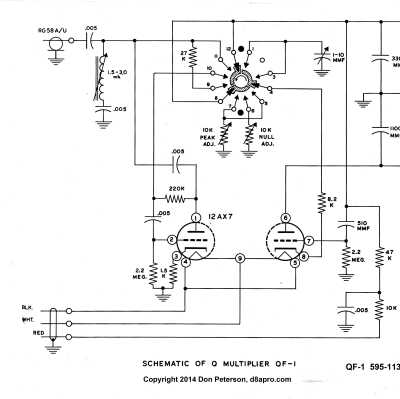
Designed around a single 12AX7, the QF-1 has no internal power supply and takes its power from the receiver to which it is connected (or some other external power source). Note that the QF-1 will not work with AC/DC type (transformerless) radios.
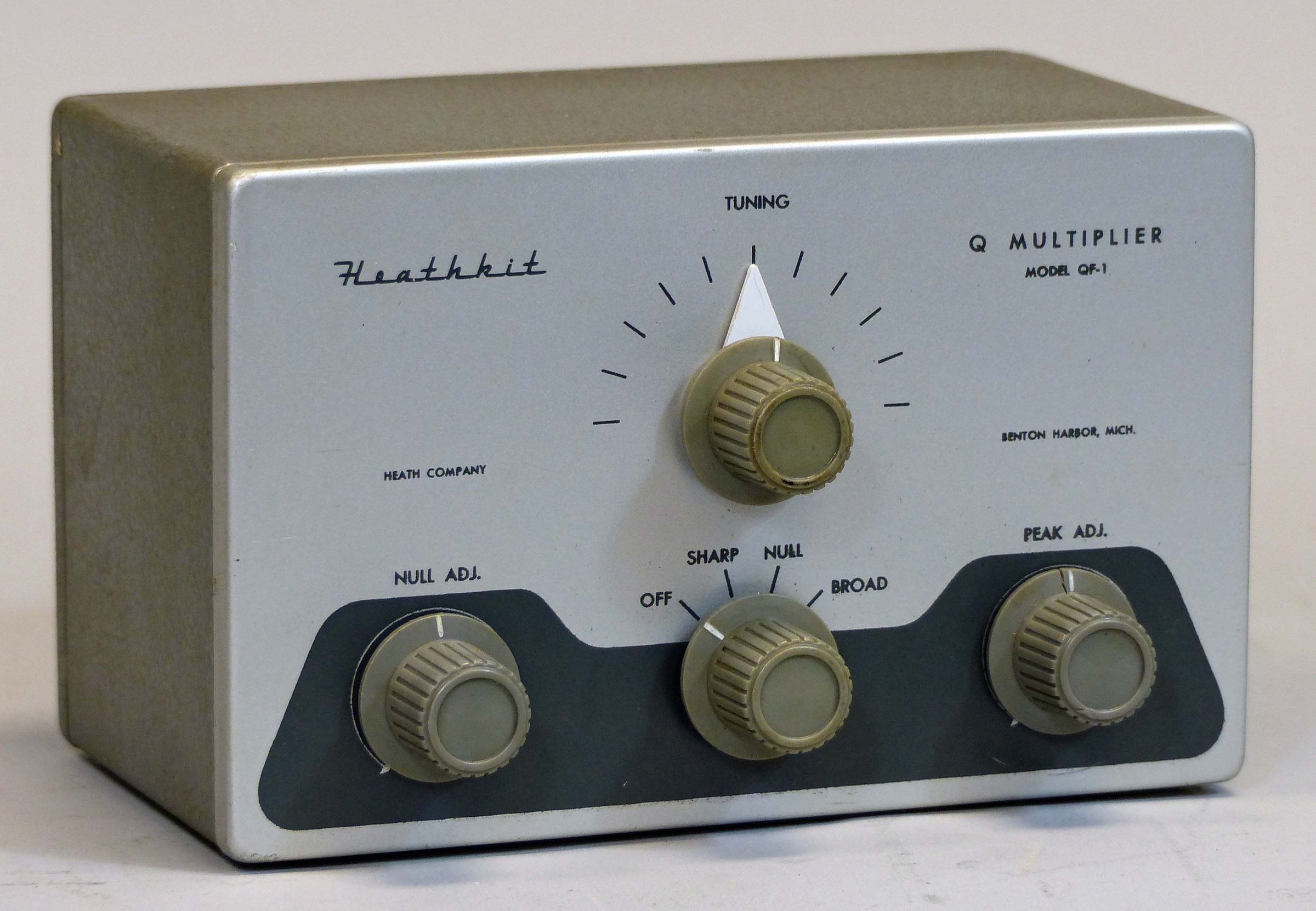
The unit uses special high-Q shielded coils to achieve an effective Q of about 4000. Front panel controls include peak, null, mode, and tuning. The tuning control has a 14:1 turns ratio for easy adjustment. The QF-1 uses the same dark gray knobs used on the DX-20, 35, and 40. Note that the NULL or PEAK knobs may or may not have skirts. The unit seems to have been supplied with different knob styles later in production.
There are two cables coming out the back panel of the QF-1. One is for connection to the receiver IF and the other has an octal plug for power input. This plug is compatible with octal sockets on the back of the AR series receivers, but it would be worth the time to check the wiring to be sure before you plug it in—just in case someone has done a modification.
The QF-1 was on the market for about four years, worked very well, and was very successful. In 1961 Heath updated the QF-1 and fitted it with an internal power supply. The new unit was designated as the HD-11. Still later the HD-11 was updated and became the GD-125. Through all of these updates, the basic circuit never changed.
There is some ambiguity regarding how much B+ should be provided. The specifications page of the assembly manual lists B+ as 150 to 250 volts. But the “Connection to Receiver” diagram in the manual states 150 to 300 volts.
The QF-1 uses the silver and gray colors of the DX-100, et al. The QF-1 is still fairly common at flea markets, though clean units in good condition are seen a bit less often.
Although deleted from the catalog after 1960, the QF-1 appeared once more in a discontinued-item sale flyer mailed in April 1962.
CONNECTIONS
If used with a receiver other than the Heath “AR” series, power cable connections are as follows:
cable shield: ground
red wire: B+
white and black: filaments (6.3 volts)
The IF coaxial cable shield should be connected to receiver chassis ground, and the inner conductor should be connected to the plate side of the IF input transformer, or the plate connection to the mixer tube at the socket.
References:
Brief description. Radio News, Mar 1956, p. 122.
Review. QST. Apr 1956, p. 39.
Variable bandwidth for. QST. May 1958, p. 77.
Extending range. QST. Jan 1964. p. 62.
Operating frequency range: 450 to 460 kHz
Functions: off, sharp peak, null, broad peak
Power requirements: 150-250 VDC at 2 mA and 6.3 volts AC or DC at 300 mA.
Tube: (1) 12AX7
Photos, general information and specifications from "Heathkit: A Guide to the Amateur Radio Products," by Chuck Penson, WA7ZZE. Used with permission.