Note
The AT-1 was introduced in Heath’s 1953 spring flye and appeared on the pages of QST in July of that same year, along with the AR-2 and GD-1A. The AT-1 was Heath’s first serious enty into ham radio and as a result, it is highly sought after by collectors. Inspired by the creation of the Novice class license, this radio stormed the novice market and set Heath on a course for fame and fortune.
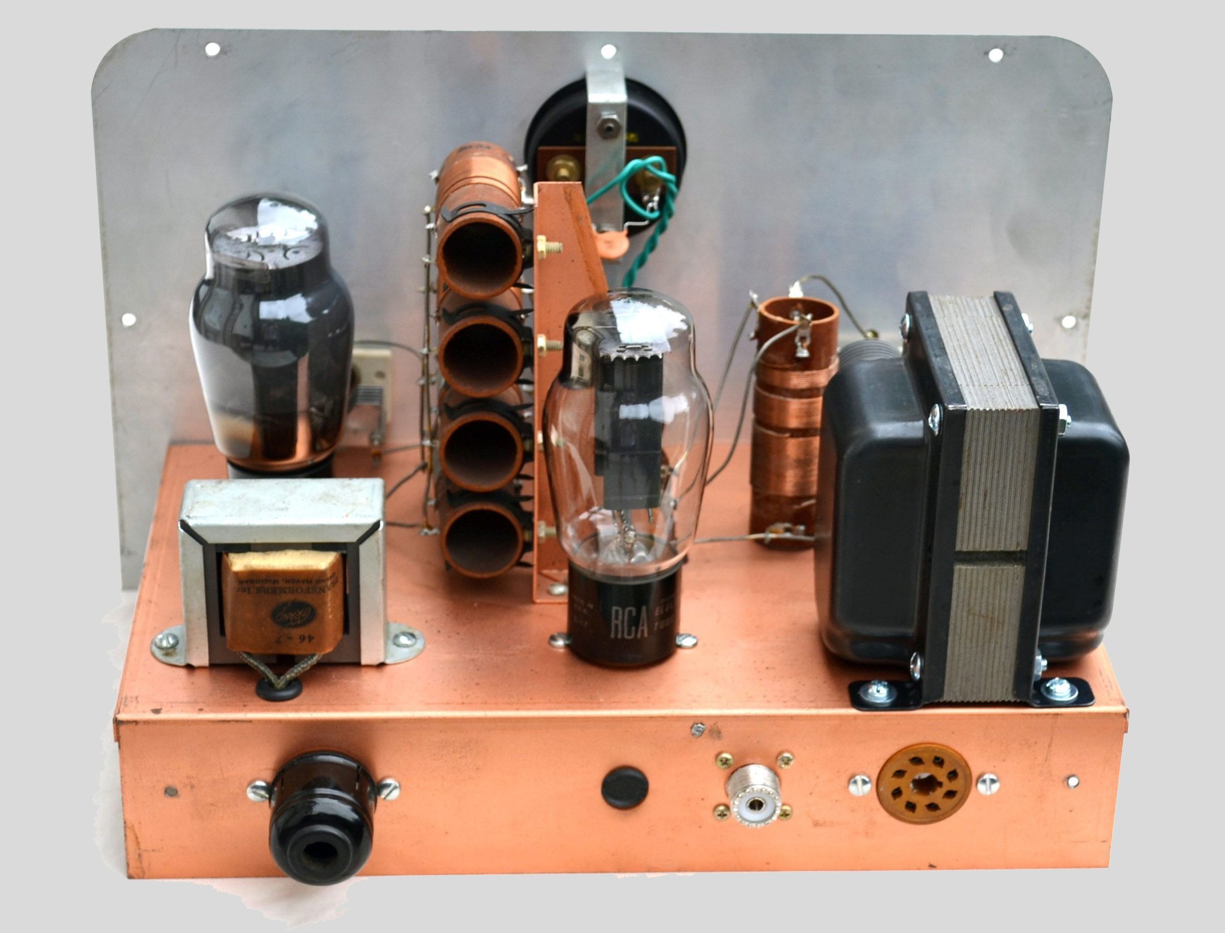
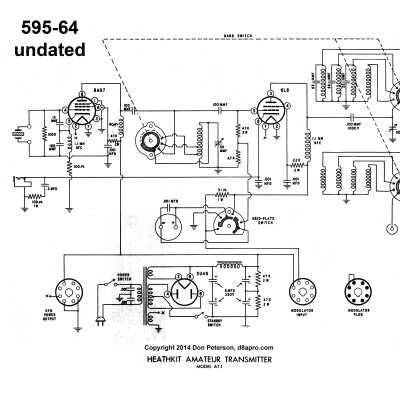
While it was just a basic three-tube design (5U4, 6AG7, 6L6), Heath included some nice features. For example, there were provisions for a mod ulator (though Heath never made one) and a VFO. Additionally, the AT-1 included an internal power supply, was built on a copper plated chassis, and incorporated single-knob band switching—no need to swap coils. The final input powe is from 25 to 35 watts, depending on which ad you read, with coverage from 80 through 10 (including 11) meters.
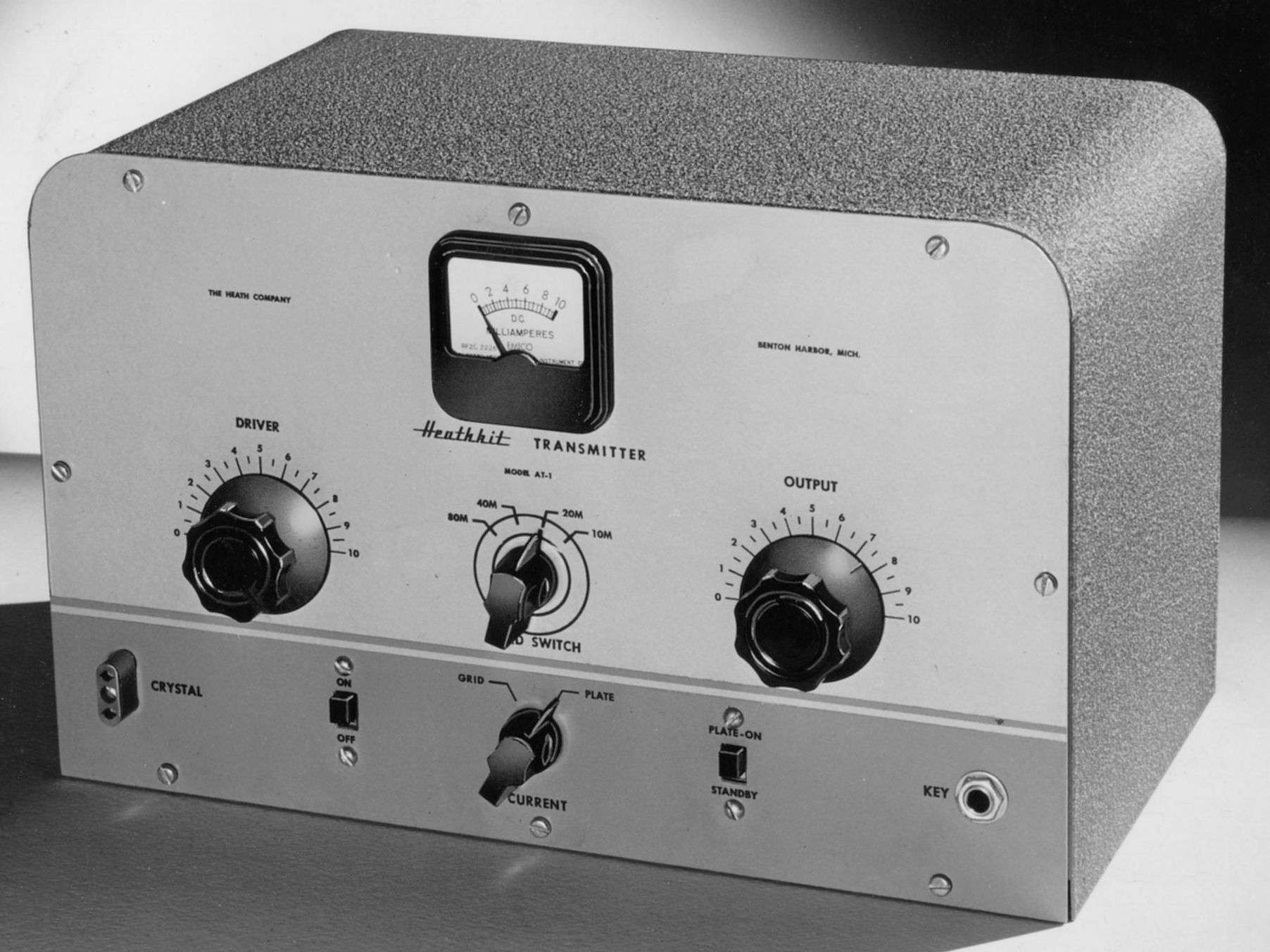
Early units were fitted with black “Collins-like” knob while later models used gray DX-20 style knobs without pointers. Note that the panel meter used on the AT-1 is not the same one used on the DX-20 or DX-35 transmitters.
The AT-1 meter has no zero adjustment, has a small hump covering the pivot point, and does not say “Heathkit.” It is not uncommon to find T-1s with other meters installed. There were, however, variations in the crystal socket and key connector used in the rig.
The rear panel contains two octal sockets. The socket on the right (as seen from the rear) provided power for the VF-1 (or other) VFO (released about a year after the AT-1). The left socket is for connection to a modulator. If a modulator is not connected, a plug with a jumper between pins 3 and 4 must be installed for normal operation. Such a plug was provided by Heath.
AT-1 operation on 11 and 15 meters is done with the band switch in the 10 meter position.
Caution: The AT-1 is not fuse protected.
Warning: Nearly 200 volts is present across the key.
The following is a list of frequency ranges, and the crystal frequencies required.
Band/Frequency Range Crystal Frequency Range
80m (3500-4000 kHz) 3500-4000 kHz
40m (7000-7300 kHz) 3500-3650 kHz
20m (14000-14350 kHz) 3500-3587.5 OR 7000-7175 kHz
15m (21000-21450 kHz) 5250-5362.5 kHz
11m (26960-27230 kHz) 6740-6807.5 kHz
10m (28000-29700 kHz) 3500-3712.5 OR 7000-7425 OR 14000-14850 kHz
In 1956 the AT-1 was replaced by the DX-20 . The DX-20 was in turn replaced by the HX-11, which was the last of the line, in 1961. Heath didn’t make another CW-only transmitter until 1979 (the HX-1681).
References:
More power. QST. Oct 1955, p. 36.
Modulating the AT-1. Radio News, Feb 1956, p. 114.
Use on 160 meters. QST. Jun 1956, p. 77.
Modulator. Radio News, Feb 1956, p. 114
Modulator. QST. Nov 1956, p. 36.
Use on 6 meters. QST. May 1957, p. 22.
Double the output. Popular Electronics, Jul 1957, p. 55.
Modulator for. Popular Electronics, Aug 1957, p. 53.
Modifications, very brief, no detail. QST. Dec 1957, p. 65.
Use VF-1 to drive on 15 meters. QST. Jun 1959, p. 62.
Overview. Electric Radio. Aug 2004, p. 83.
Overview. QST. Dec 2016, p. 102.
Revisiting. Electric Radio. Dec 2015.
Meter movement. Electric Radio. Oct 2016.
Cathode modulator. Electric Radio. Apr. 2017.
Overview. QST. Oct. 2018, p. 89.
RF amplifier power input: 25-30 watts
Output connection: 50Ω, SO-239
Oscillator operation: crystal, or optional VFO
Amplifier operation: CW, or phone with external modulator
Band coverage: 80, 40, 20, 15, 11 and 10 meters
Power requirements: 120 VAC, 50/60 Hz, 100 watts
Tubes: (1) 5U4, (1) 6AG7, (1) 6L6
Photos, general information and specifications from "Heathkit: A Guide to the Amateur Radio Products," by Chuck Penson, WA7ZZE. Used with permission.