Note
QST, Dec 1957, p. 129.
QST. May 1959, p. 145. (specs, "Now in full production.")
QST, Feb 1961, p. 149. (limited quantities)
CQ, Mar 1961, p. 120. ("just a few left")
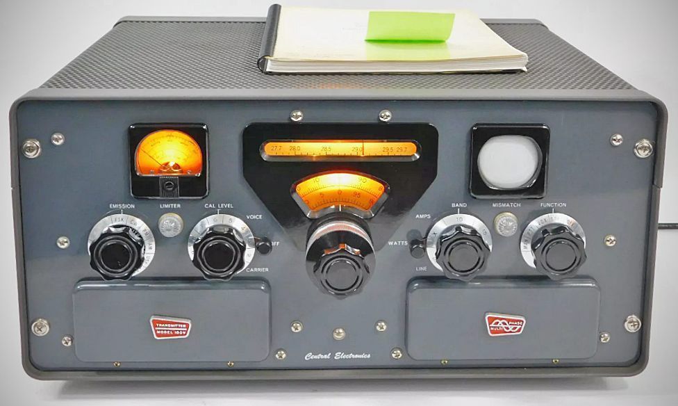
Only a few years after Central Electronics entered the commercial market with relatively simple sideband gear, they introduced the complex and sophisticated 100V transmitter late in 1957. A subtle refinement, the 200V, appeared in 1961.
The core engineering feature of the 100V is its "No Tuning" broadband design. Using patented Multiphase No Tuning Broadband Couplers, all stages between the balanced modulator and the RF output are fixed-frequency or bandpass. Consequently, the operator only has a single tuning control to manage: the VFO. A single-knob band switch selects all bands.
The two-speed VFO knob turned a linear PTO, which had 1 kHz calibration on all bands. The slow tuning rate was 750Hz per knob revolution. True to Central Electronics form, it used the phasing method of sideband generation. Power output was 100 watts PEP. It covered 80-10 meters with a spare band-switch position for 160 meters or non-ham-band operations.
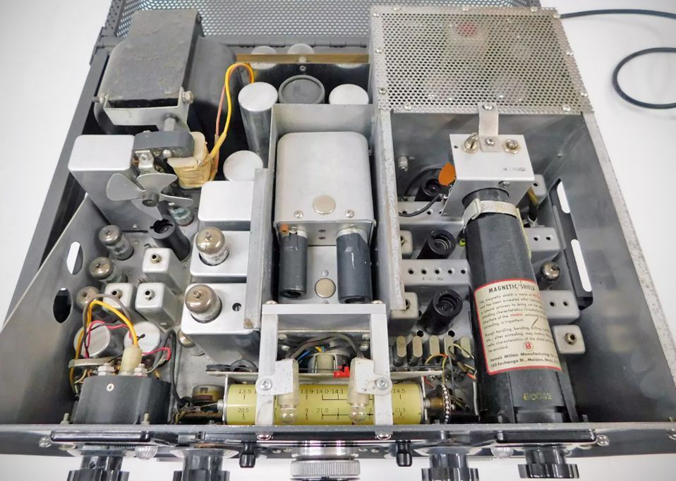
The VFO uses a permeability-tuned circuit driven by a precision stainless steel lead screw mounted in preloaded ball bearings. The oscillator circuit incorporates a U.S. patent (#2,867,725) to self-compensate for changes in tube transconductance caused by aging or line voltage fluctuations.
Frequency is read directly in 1 kHz increments via a circular window, backed by a rotating slide-rule "Megacycle" scale linked to the bandswitch.
Frequency drift is rated at less than 25 cycles in any 10-minute period after a 5-minute warm-up.
The VFO operates from 5 to 6 MHz and heterodynes against crystal-controlled oscillators or a master 8 MHz signal. Because the sideband generator operates at a fixed, crystal-controlled frequency, rebalancing the carrier is unnecessary when switching bands. For maximum stability, all oscillators run continuously. Mixers and linear amplifiers use blocked-grid keying for clickless, chirp-free operation.
Advanced Phasing SSB Generator
Rather than using a traditional filter approach, the 100V uses an advanced phasing method for SSB generation:
– PS-2 Audio Phase Shift Network: Constructed with heat-cycled components matching 1% accuracy, providing at least 50 dB of unwanted sideband suppression across a 200 to 3800 Hz range.
– Inverse Feedback: Uses 35 dB of inverse feedback around the modulator system to ensure long-term audio amplitude balance, allowing modulator tubes to be changed without degrading sideband suppression.
– Carrier Suppression: Stable in excess of 50 dB below maximum output, which can be monitored directly on the front panel meter.
Perhaps the most obvious feature of the transmitter is a 2-Inch oscilloscope. The scope uses a 2AP1 CRT that continuously monitors the linearity of all stages from the balanced modulator to the RF output, as well as indicating AM modulation percentage.
An illuminated 2-inch rectangular meter capable of reading final amplifier Power Input (0-200 Watts), RF Output Current (0-1.5 Amps), Carrier Suppression (in dB), or AC Line Voltage.
Features
The 100V provides continuous, constant power output across five primary amateur bands:
80 meters: 3.5 to 4.5 MHz
40 meters: 6.5 to 7.5 MHz
20 meters: 13.5 to 14.5 MHz
15 meters: 20.5 to 21.5 MHz
10 meters: 27.7 to 29.7 MHz
Note: A spare position is available on the bandswitch to install custom broadband couplers for 160 meters (1750 to 2500 kHz) or other 1 MHz segments of the spectrum starting and ending at 5 MHz points.
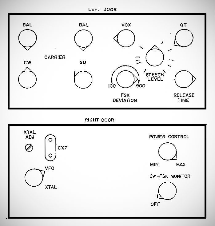
Seldom-used adjustments (such as Speech Level, VOX Trip, Anti-Trip, VOX Release Time, Carrier Null, Power Output, and FSK Deviation) are concealed behind two magnetic doors on the front panel to keep operation simple.
Other features include a limiter indicator: A neon bulb showing speech clipping depth (3 dB normal, up to 10 dB for adverse conditions).
There is also a mismatch indicator which connects to a screen grid overcurrent relay; if excessive SWR occurs, it adds protective grid bias, lights the indicator, and sounds an audible alarm.
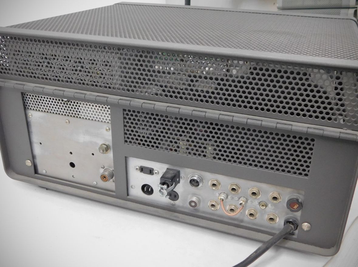
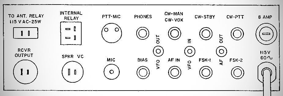
Output Impedance: Designed to match unbalanced 50 to 72 ohm coaxial loads (UHF SO239 receptacle).
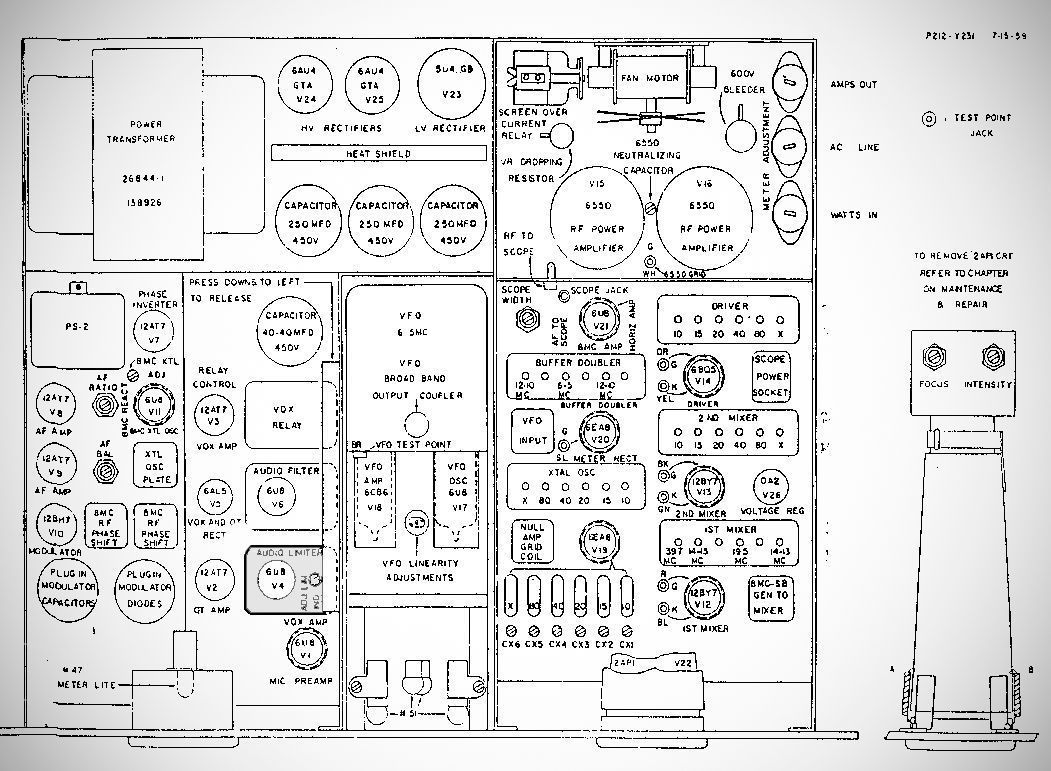
Tube Lineup (26 total)
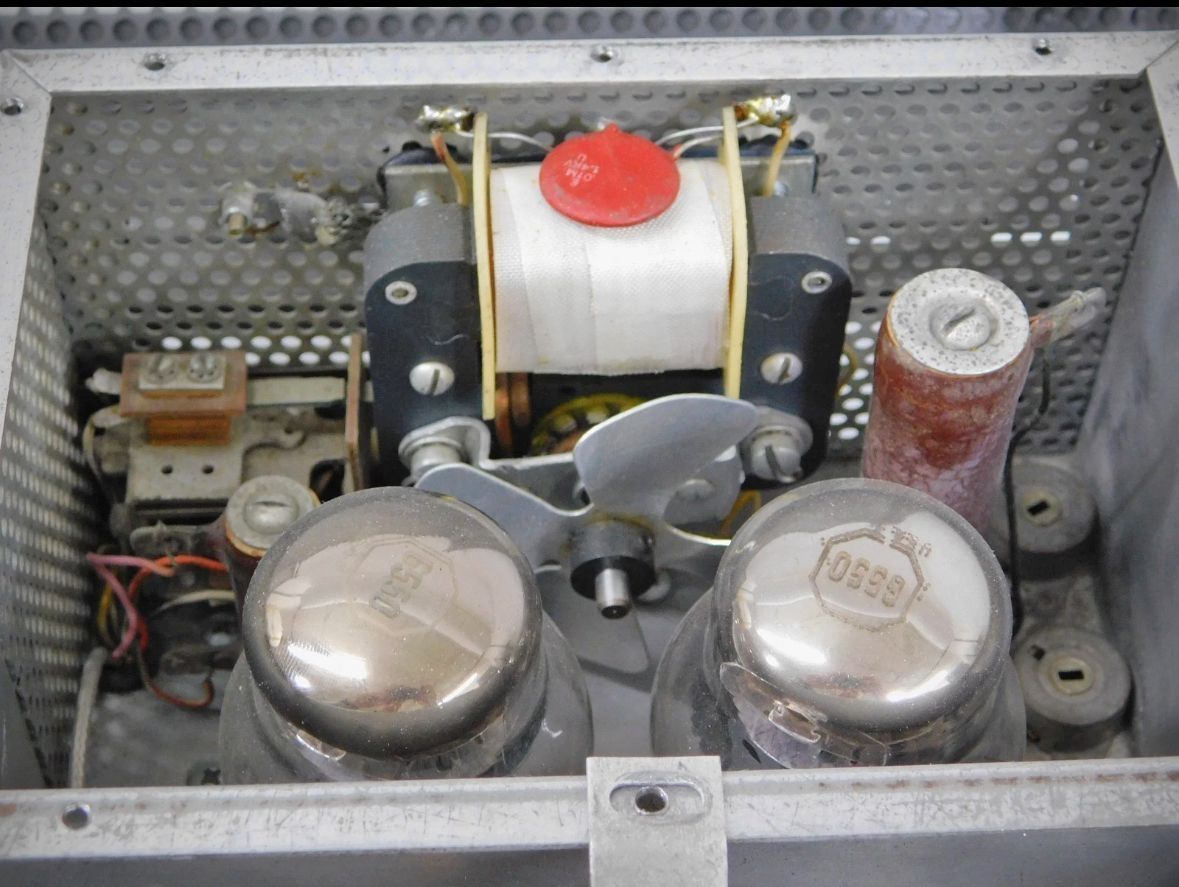
– (2) 6550 Final RF Power Amplifiers (operated in parallel)
– 6BQ5 RF Driver
– (2) 12BY7 First and Second Mixers
– 12AX7 Microphone Amplifier and Limiter
– 6AL5 Audio Limiter Rectifier
– (2) 12AT7 Audio Cathode Followers
– (2) 12AT7 Balanced Modulators
– 6U8 VFO and Buffer
– 6U8 Crystal Oscillator and Mixer
– 6U8 8 MHz Crystal Oscillator and Calibrate Amplifier
– 12AX7 VOX and Anti-Trip Amplifiers
– 6AL5 VOX and Anti-Trip Rectifiers
– 12AU7 VOX Relay Tube and FSK Keyer
– 2AP1 Cathode Ray Tube
– 12AT7 Deflection Amplifier
– 5U4GB High Voltage Rectifier
– (2) 6AU4GT Low Voltage Rectifiers
– (2) OA2 Voltage Regulators
– OB2 Voltage Regulator
Power Requirements:
115 VAC, 5/60 Hz