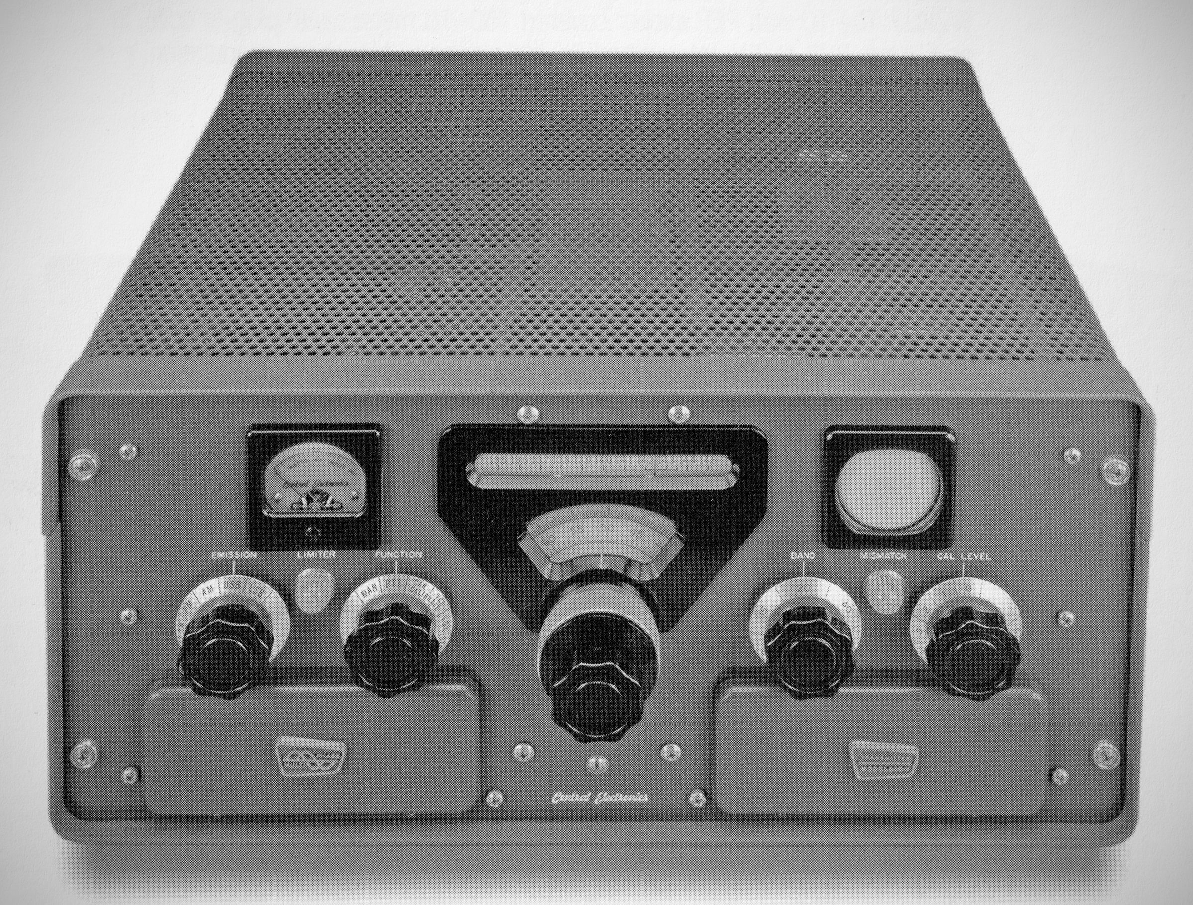
Note
QST, Feb 1961, p. 103.
CQ, Feb 1961, p. 6.
QST, Dec 1961, p. 115. (technical notes)
The Central Electronics 200V, introduced in 1961 as the successor to the highly innovative 100V, brought several refined design improvements that cemented its status as one of the ultimate transmitters of the era.
Designed by Wes Schum (W9DYV) and lead engineer Joe Batchelor, it expanded upon the groundbreaking no-tune broadband circuitry of the 100V while addressing several key areas of performance, stability, and power.
The primary improvements included:
1. Enhanced Speech Processing: The "Inverse Limiter"
While simple audio clipping often introduces harsh distortion and harmonic splatter, the 200V introduced a new circuit called the Inverse Limiter.
This system took the clipped audio waves and fed them back as inverse feedback to cancel out the distortion products. Combined with a perfected RC audio filter network, it allowed up to 10 dB of RF speech compression to give the audio "punch" in heavy QRM without ruining the signal quality or overloading the mixer stages.
2. Upgraded Dial Layout
No Reverse-Reading Scales: A common frustration on many vintage multi-band rigs was reading mirrored or reversed dial scales depending on the band. The 200V eliminated this entirely—all scales read directly left-to-right.
3. Improved Frequency Stability (Double Heterodyne)
The 200V implemented a new double heterodyne mixing scheme to maximize frequency stability.
The Permeability Tuned Oscillator (PTO) VFO was isolated to tune between 5.0 and 6.0 MHz, while sideband generation was fixed and crystal-controlled at 8.0 MHz. All heterodyne oscillators ran continuously, were temperature-compensated, and were tightly regulated to eliminate drift.
4. Solid-State Power Supply (Silicon Rectifiers)
The power supply moved away from conventional, heat-generating vacuum tube rectifiers in favor of silicon rectifiers.This significantly reduced internal cabinet temperatures (extending component life) and yielded vastly superior voltage regulation under heavy, dynamic SSB voice peaks or continuous 100% key-down CW/RTTY operation.
Features retained from the 100V:
– Completely broad-banded.
– Frequency coverage: 80-40-20-15-10 meter bands.
– Input 175 watts on CW, FSK and PM. 100 watts on AM.
– Two-speed tuning mechanism
– Calibration accuracy better than 1 kHz
– "Tailored" audio filter-audio limiter.
– Adjustable power output control.
– 2" monitoring scope.
– Unwanted sideband suppression 50 dB.
– Carrier suppression at least 50 dB.
– Harmonics down in excess of 50 dB.
– Third order distortion products down in excess of 40 dB.
⚠️See entry for 100V for additional information.
Tube Lineup (23 total)
⚠️ Note: The tube lineup is substantially different from the 100V. Also, tube numbering goes to V26, but three tubes (V23, V24, and V25) have been deleted since the 100V on which the numbering system is based)
– (2) 6550 Final RF Power Amplifiers (operated in parallel)
– 6BQ5 RF Driver
– 6EH7 1st Mixer
– 6EJ7 2nd Mixer
– 0A2 Voltage Regulator
– 6BL8 Microphone Amp / VOX Amp
– 6AB4 Crystal Oscillator
– 6CB6 VFO Doubler / Buffer
– 6BC8 8 MHz AMp / Horiz Amp
– 6CB6 VFO Amp
– 6BL8 VFO
– 6BL8 Reflex Limited Indicator Amp / Inverse Limiter
– 6BL8 AF Amp
– 12AT7 Relay Control / VOX Amp
– 6AL5 VOX Rectifier / QT Rectifier
– 12AT7 QT Amp
– 6BL8 8 MHz Osc / Reactance Tube
– 12AT7 Audio Phase Inverter
– 12AT7 Audio Amp
– 12AT7 Audio Amp
– 12BH7 AF Modulator
– 2AP1 Cathode Ray Tube