Note
QST, Mar 1961, p. 121. (First ad for Clegg.)
QST, Jan 1964, p. 135.
QST, Mar 1965, p. 121.
Initially called the "Climaster Zeus."
The driving force behind Clegg designs was Edward T Clegg, W2LOY (also W3 and W8LOY).
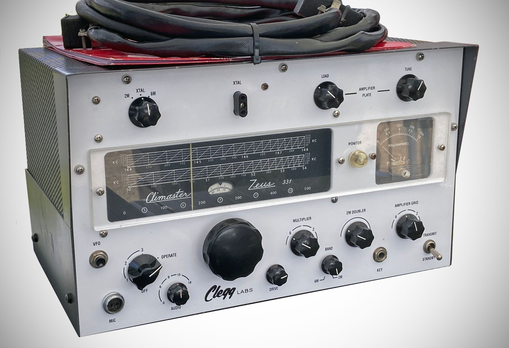
The Clegg Climaster Zeus (often simply referred to as the Clegg Zeus) is a high-power VHF transmitter manufactured by Clegg Laboratories (a division of Clegg, Inc. based in Mt. Tabor, New Jersey) during the early 1960s. Regarded as a pinnacle of AM and CW engineering for the 6-meter and 2-meter amateur radio bands, the Zeus is known for its robust physical construction, highly stable internal VFO, and exceptional audio quality.
The Zeus 6 and 2 meter transmitter featured a handsome Eddystone dial and had a power output of 125 watts AM and CW. The transmitter's clipper-filter circuit (called Automatic Modulation Control) gave it additional talk power on AM.
The VFO dial utilizes an unconventional "diagonal line" interpolation system. The scale has diagonal lines intersecting horizontal tracks. Each major marker represents 250 kHz, subdivided by diagonal lines into 50 kHz steps. This visual projection system allows operators to manually reset or set the VFO frequency to within 10 kHz accuracy. Additionally, the dial has a non-linear format to stretch and provide maximum bandspread in the most active portions of the 6m and 2m bands.
Speech Clipping & Automatic Modulation Control (AMC)
One of the Zeus's defining characteristics is its "talk power". It features a symmetrical low-level speech clipper consisting of 1N34A germanium diodes alongside an active AMC system. A front-panel control allows up to 18 dB of usable speech clipping. A negative peak detection circuit (using a 6W4) begins restricting clipper bias within 100 microseconds of encountering a modulation peak exceeding 90%. A front-panel MONITOR neon glow lamp flashes to show peak modulation and signal when active clipping begins.
The transmitter is split into two distinct, physically separate units connected by an interconnecting cable:
1. Model 331 RF Unit – Usually placed on the operating desk.
2. Model 332 Modulator/Power Supply Unit – A very heavy auxiliary chassis that can be placed remotely.
Specifications
– Frequency Coverage: Fully covers the 6-meter band (49.5 to 54.1 MHz) and the 2-meter band (143 to 148.5 MHz), as well as associated MARS frequencies.
– Frequency Control: Stable built-in internal VFO or panel-selected crystal control.
– 6-meter crystal range: 8.333 to 9.000 MHz and 12.500 to 13.500 MHz (12–13 MHz crystals are recommended to minimize TVI).
– 2-meter crystal range: 8.000 to 8.222 MHz and 12.000 to 12.333 MHz.
– Power Ratings: 150 to 180 watts carrier input, yielding approximately 100 to 120 watts of carrier output.
– Output Impedance: 40 to 80 ohms nominal.
Tube Lineup (21 total)
RF Unit (Model 331)
– 6BK7B VFO/Oscillator
– 6AH6) Buffer
– 6CL6 Multiplier
– 7558 2-Meter Doubler
– 7558) Driver
– 7034 / 4X150 Final Power Amplifier
Low-Level Audio (RF Unit)
– 12AX7 Low-level preamplifier stage
– 12AU7 Low-level preamplifier stage
Modulator & Power Supply Unit (Model 332)
– 12AT7 Cathode-coupled phase inverter
– 6BX7 Push-pull, direct-coupled cathode follower driver
(2) 811-A Dual zero-bias triodes operating in Class B push-pull high-level plate/screen modulation.
– 6W4 Automatic Modulation Control (AMC)
– 6C4 Automatic Modulation Control (AMC)
– 5U4G Full-wave rectifier for the 325V low-voltage supply.
– OA2 Voltage regulator tube providing 150V regulated DC to the oscillator and buffer.
(2) 3H7 / Amperite Cascaded ballast tubes to regulate VFO filament current and stabilize frequency against line voltage
(2) 5R4GY Rectifiers providing high-voltage 875V DC.
– 6BX7GT DC clamp tube used to protect the screen grid of the final amplifier.
Power Requirements: 115 VAC, 58–62 Hz, drawing approximately 600 VA.
References
QST, Mar 1962, back cover. (info about finals)