Note
QST, Apr 1962, p. 125.
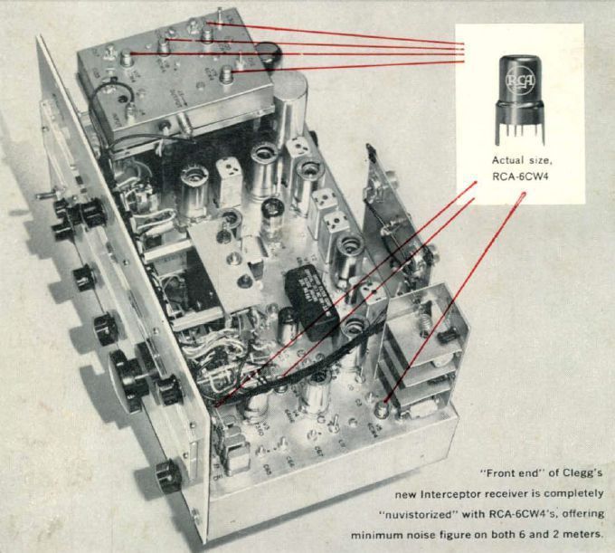
QST, Oct 1962, back cover. (inside view, tech details)
QST, Dec 1963, p. 131. ("B" version)
QST, Jan 1964, p. 135.
QST, Mar 1965 p. 121.
The Interceptor was the companion piece to Clegg's Zeus 6 and 2 meter transmitter.
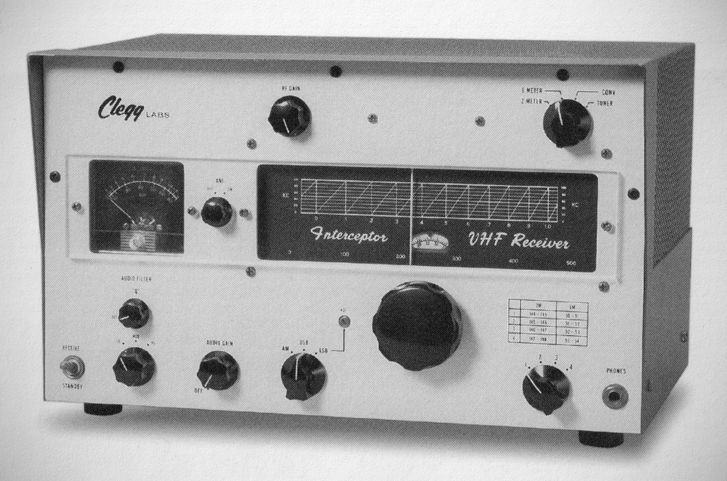
The Clegg Interceptor is a high-performance VHF receiver designed for the 6-meter and 2-meter amateur radio bands. it was styled to match the cabinet and panel design of the Zeus transmitter .
Features
Bands & Coverage: Designed for 6 and 2 meters. It includes input provisions for connecting 220 Mc, 432 Mc, and other UHF converters.
RF Circuitry: Features Nuvistor RF stages to achieve minimal noise figures across both 6 and 2 meters.
Sensitivity & Tuning: Offers a sensitivity better than 0.1 microvolts. It features a slide rule dial with full electrical band-spread, flywheel-loaded, no-backlash tuning, and frequency tuning accuracy of less than 3 kc in calibrated 1 Mc ranges.
Selectivity & Filtering: Employs a hermetically sealed 10.7 Mc crystal lattice filter designed for both AM and SSB. Selectivity is rated at 3.1 kc at 6 dB points and 8 kc at 75 dB points.
Interference & Cross-Modulation Handling: Features virtually no cross-modulation, maximum rejection of spurious signals and responses, and a specially designed noise limiter for maximum hash suppression. The receiver sensitivity and selectivity allow for duplex operation (on antennas separated by no less than 60 feet) with stations transmitting within 25 kc of the operating frequency.
Metering & Connections: Includes a tuning meter calibrated in both S-units and dB above reference, as well as an output terminal for a Pan-adapter and monitoring scope.
Specifications
– Tuning Range: 49.95 to 54.1 mc and 143.95 to 148.1 mc.
– Band Coverage: Covers the amateur 6-meter and 2-meter bands via 8 separate, overlapping 1 MHz ranges.
– Dial Calibration: Readable ±3 kHz; resettable via vernier to 1 kHz.
– Frequency Drift: Less than 100 Hz per hour after a 15-minute warmup; total warmup drift is less than 1 kHz at room temperature.
– BFO: Crystal-controlled.
– Sideband Selection: The mode switch automatically shifts the tuneable oscillator when switching between upper and lower sidebands.
– IF Selectivity:
Sharp: 3.1 kHz at 6 db, 8 kHz at 60 db
Broad: 6 kHz at 6 db, 20 kHz at 60 db
– Crystal Lattice Filter: Switchable filter providing a sharp 3.1 kHz skirt selectivity for SSB/CW and a 6 kHz bandpass for strong AM signals and net operation.
– Sensitivity: 0.1 microvolt or better for a 10 db S/N ratio.
– Dynamic Range: Greater than 120 db.
– Overload Characteristics: Less than 5% cross-modulation of a 1 microvolt signal by a 25 microvolt signal.
– Spurious Responses: Spurious and image responses are down by at least 80 db; IF leak through is down by at least 90 db.
– Detectors:
Infinite impedance detector for AM.
Product detector for CW/SSB.
– Noise Limiters: Two full-wave series-type limiters:
Automatic type for AM (clips at 60% level).
Manually adjustable threshold type for SSB and CW.
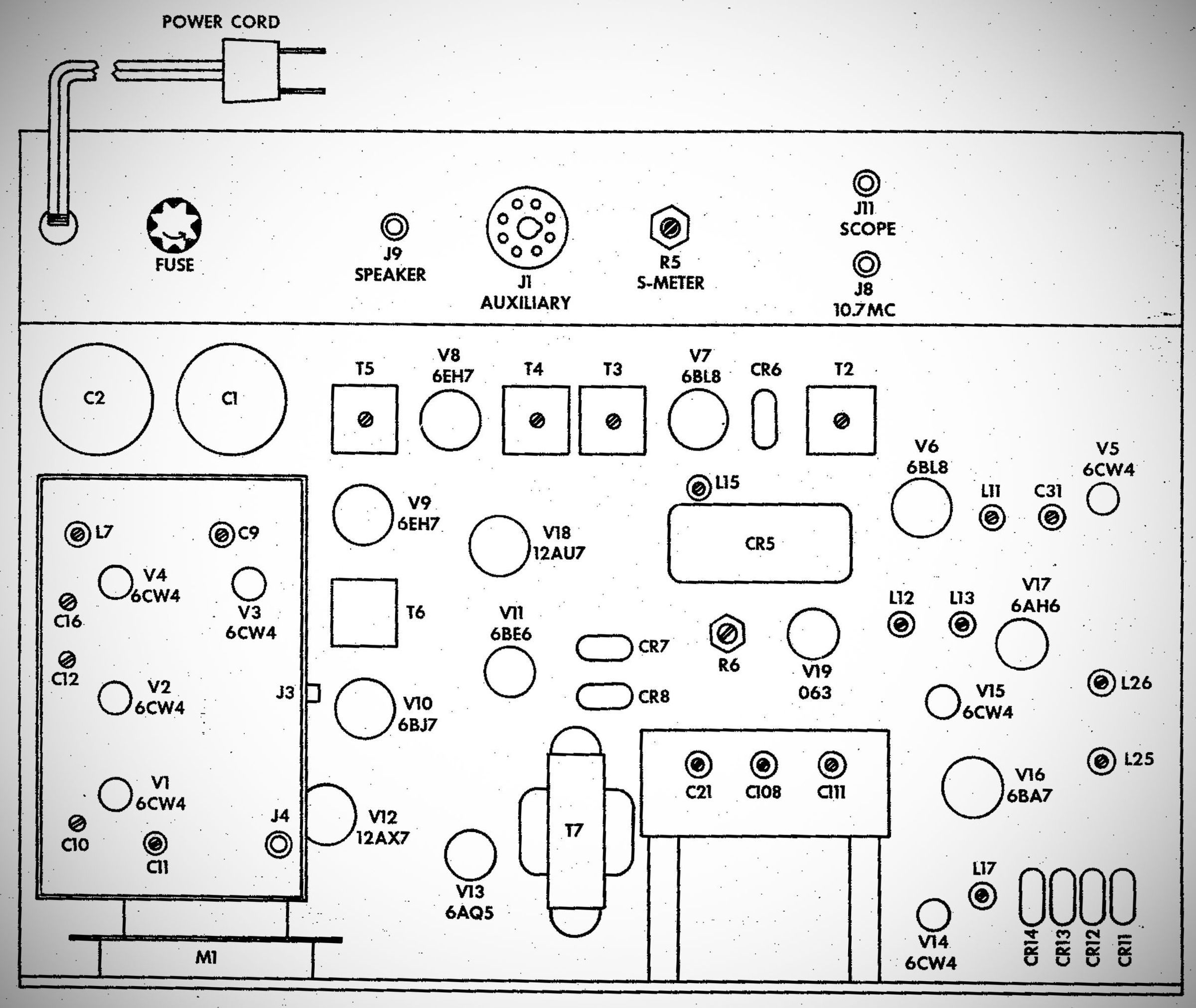
Tube Lineup ("B" model) (19 total)
– (7) 6CW4
– (2) 6BL8
– (2) 6EH7
– 6BJ7
– 6BE6
–12AX7
– 6AQ5
– 6BA7
– 6AH6
– 12AU7
– 0B3
Power requirements: 117 VAC, 60 Hz