Note
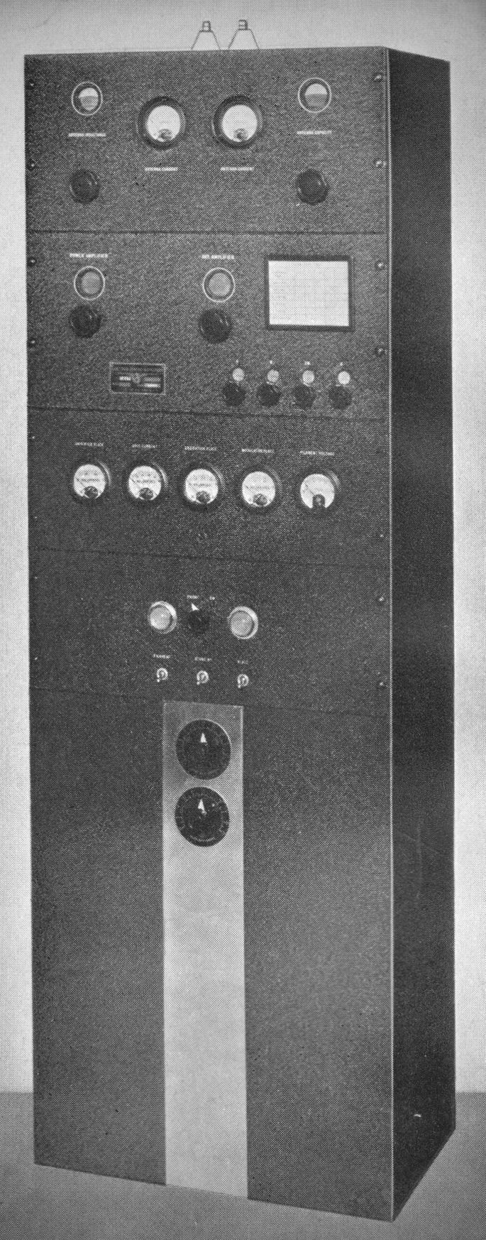
The Collins 30FXC represents the high-water mark of mid-1930s engineering. Introduced in 1935, it was designed as a high-fidelity, multi-frequency transmitter for both amateur radio and commercial applications. In 1935, the 30FXC cost roughly $975.00. To put that in perspective, a brand-new Ford Tudor sedan cost about $500.00 at the time. This was an investment piece intended for serious stations, government agencies, and the wealthiest amateurs.
Technical Specifications & Design
The 30FXC is a floor-standing, cabinet-style transmitter. It wasn't just built to transmit; it was built to last several lifetimes.
– Power Output: Rated for 175 Watts (CW and Phone/AM).
– Frequency Range: It covered 1.5 to 30 MHz.
– The "C" Designation: The "C" in 30FXC stands for Cabinet. While the 30FX was often sold as a rack-mount system, the "C" version came housed in a professional-grade steel enclosure.
Tubes
– Oscillator: C100A (A unique, external-grid vacuum tube designed by Collins and Dr. Robert Goddard to bypass RCA patents).
– Frequency Multiplier: 46 (Single or cascaded pair depending on the frequency band).
– Intermediate Amplifier (Driver): RK20 (Pentode).
– Power Amplifier (Final): Collins C201 (The high-power triode that delivers the 175-watt carrier).
Audio (Modulator) Section
Speech Amplifier: Designed to handle the then-new Astatic D-104 crystal microphone.
– 2A3s or 56s were common in early stages (depending on the specific revision of the 7C speech amp).
– Modulators: RK31 (A pair operated in Class B).
Note: Type 830B tubes were the factory-authorized alternate for the RK31.
Power Supply Section
– High Voltage Rectifiers: 866A (A pair of heavy-duty mercury vapor rectifiers).
– Low Voltage/Bias Rectifiers: Typically 5Z3 or 80 series.
Key Features
1. High-Fidelity Audio
Unlike many home-brew rigs of the 1930s, the 30FXC was engineered for broadcast-quality audio. It used a sophisticated modulation transformer that allowed for a very clean, wide-range voice signal.
2. Frequency Control
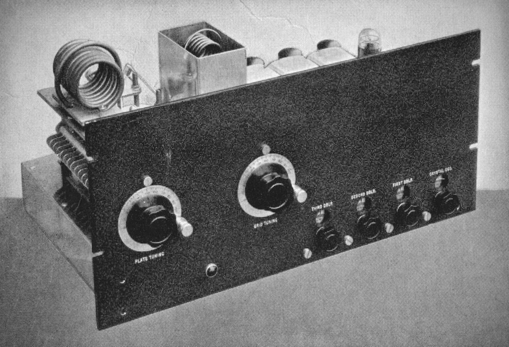
The unit utilized the Collins 2C Exciter.
3. Iconic Aesthetics
The front panel is a masterclass in industrial design, featuring:
– Large, easy-to-read Weston meters.
– Symmetrical dial layouts.
– Heavy-duty switching gear that provides a satisfying "clunk" when changing bands or powering up.
The 30FXC transmitter could be supplied with the 10X RF Unit to amateurs who are particularly interested in the higher frequencies. The 10X RF Unit requires the same panel space as the 10M unit ordinarily supplied but it employs a special tube and circuit arrangement adapted to the higher frequencies.
The tubes are:
(1) C100A Oscillator
(1) 6L6 First Frequency Multiplier
(1 ) 6L6 Second Frequency Multiplier
(2) 6L6 Third Frequency Multiplier
(2) C800 or 2-C101 Power Amplifiers
The frequency range of the type 10X is 10 to 60 MHz. The nominal plate input to the C800's in the final amplifier is 150 watts, giving an output of 100 watts at the lower radio frequencies and 60 to 75 watts at the highest radio frequency. The output circuit of the 10X is similar to that of the 10M and may be used with non-reactive high frequency lines, or it may be supplied with a matching network. Frequency change can be accomplished by means of plug-in coil assemblies. Both the grid circuit and the plate circuit of the final amplifier are tuned by front panel controls. All dials, including the oscillator and frequency multiplier stages are fitted with locks for fixing the position of the tuning condensers.
The standard 30FXC with 10M RF Unit for frequencies between 1.5 MHz. and 30 MHz. Power output on phone or CW is 175 watts.
The Collins 30FXC had a relatively short but impactful production run, manufactured from approximately late 1935 until late 1937.
By 1938, it had been officially phased out in favor of the Collins 30J, which Arthur Collins famously called "Our Baby" in advertisements.
The Timeline of the 30FX Series
December 1934: The base model 30FX (a desktop version) was introduced.
1935: The 30FXB and 30FXC (the "C" for Cabinet) were heavily promoted. During this year, the 30FXC became the must-have for high-end amateur and commercial stations.
April 1936: The 30FXB/C variants were still being actively promoted in major radio journals like QST.
November 1937: Collins announced the 30J transmitter. The 30J was essentially the successor to the 30FXC, offering 40% more power (250 watts vs. 175 watts) and a more modern, Art Deco-inspired cabinet.
The 30TXC was phased out for a couple of reasons:
– The RCA Patent Dispute: Collins was using "bootleg" tube designs (like the C100A) to bypass RCA’s vacuum tube patents. By 1938, Collins finally reached a licensing agreement with RCA and AT&T. This allowed them to design the next generation of transmitters (the 30J and later models) using standard RCA-type tubes like the 807 and 813, making the specialized 30FXC hardware obsolete.
– Technological Advancement: The 30FXC used a somewhat cumbersome system of plug-in coils to change bands. Newer designs in the late 30s began moving toward more efficient switching and higher power handling that the 30FXC chassis wasn't originally designed to accommodate.
Because the 30FXC was only produced for about three years during the height of the Great Depression, very few were made compared to post-war models. It remains one of the most collectible pre-war transmitters because it represents the era when Collins was fighting for its life against the "Radio Trust" (RCA).