Note
QST, Nov 1937, inside front cover.
QST, Feb 1938, inside front cover.
QST, Mar 1938, inside front cover. (good photo of RF section)
QST, Jul 1938, inside front cover.
QST, Sep 1939, inside front cover. (output to 60 MHz)
QST, Mar 1940, inside front cover.
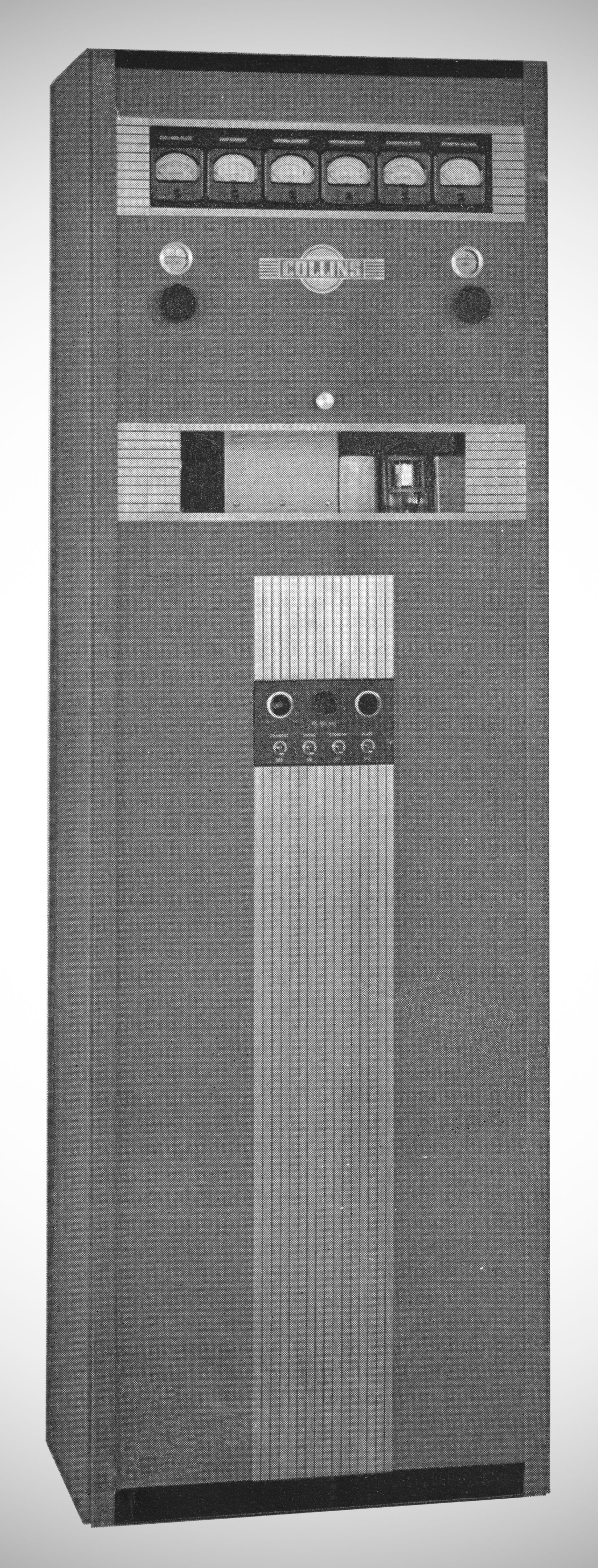
A power increase of 40% over the 30FXC. Simplified tuning has been the key note of the design.
SPECIFICATIONS
Power output: 250 watts Phone and CW.
Frequency range: 1.5 to 30 MHz (0.5 MHz. to 60 MHz. on special order).
Frequency change: Plug-in coils.
Modulation: High level, Class "B".
Crystals: "A" cut in 294 or 1A holder.
Audio frequency input: From microphone –40 db at 50,000 ohms.
Audio frequency response: Plus or minus 1.5 db from 100 to 5000 cycles.
Carrier noise: More than 40 db below 100% modulation.
Output circuit: Pi tank circuit for operation with balanced transmission line or feeder.
Mechanical features: Stream-lined cabinet. Hinged rear door. Tube access window. Rectangular instruments behind glass window. Pre-tuned excitation tank circuits adjustable through access window. Further refinements in workman-ship.
Electrical features: Simplified output circuit. Link coupling to push-pull final amplifier. Fixed grid bias. Stage by stage J;llCtering and switching. Three power supplies. Negative resistance oscillator. Beam excitation tubes. Convenient control circuits.
Tubes: (1) C100D oscillator. (1) 807 first doubler-amplifier. (1) 807 second doubler-amplifier. (3) 807 third doubler-amplifiers. (2) C101 final amplifiers. (2) 6J5G audio amplifiers. (2) 6F6G audio drivers. (2) C120 modulators. (2) C249B mercury vapor rectifiers. (2) C866A mercury vapor rectifiers. (1) 5Z3 low voltage rectifier.
Power: 110 VAC, 50-60 cycle, single phase, 1200 VA
References
Brief review. Radio, Jan 1938, p. 93.