Note
QST, Jun 1946, p. 87.
QST, Feb 1947, p. 127. (30K-1)
QST, Feb 1947, p. 100. (nice photo)
Radio News, Apr 1947, p. 21. (30K-2)
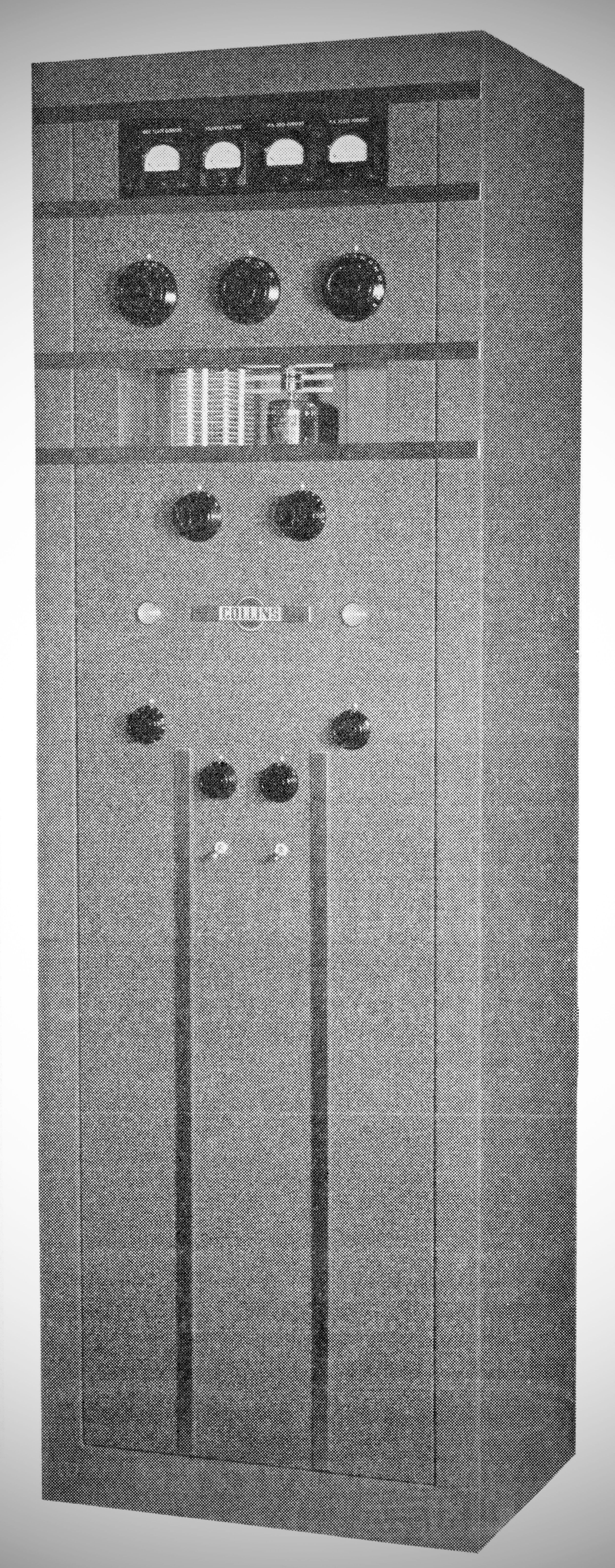
Designed by Collins engineer Warren Bruene in 1945 and released for sale the following year, the Collins 30K-1 is a rare and classic postwar amateur radio transmitter. Developed at a time when wartime contracts were drying up and ham radio was still under a temporary ban, it represented a bold move by Collins to capture a anticipated postwar market. Because of its high original cost of $1,450 in 1946, fewer than 100 units were ever built, making it an exceptionally rare piece of gear today.
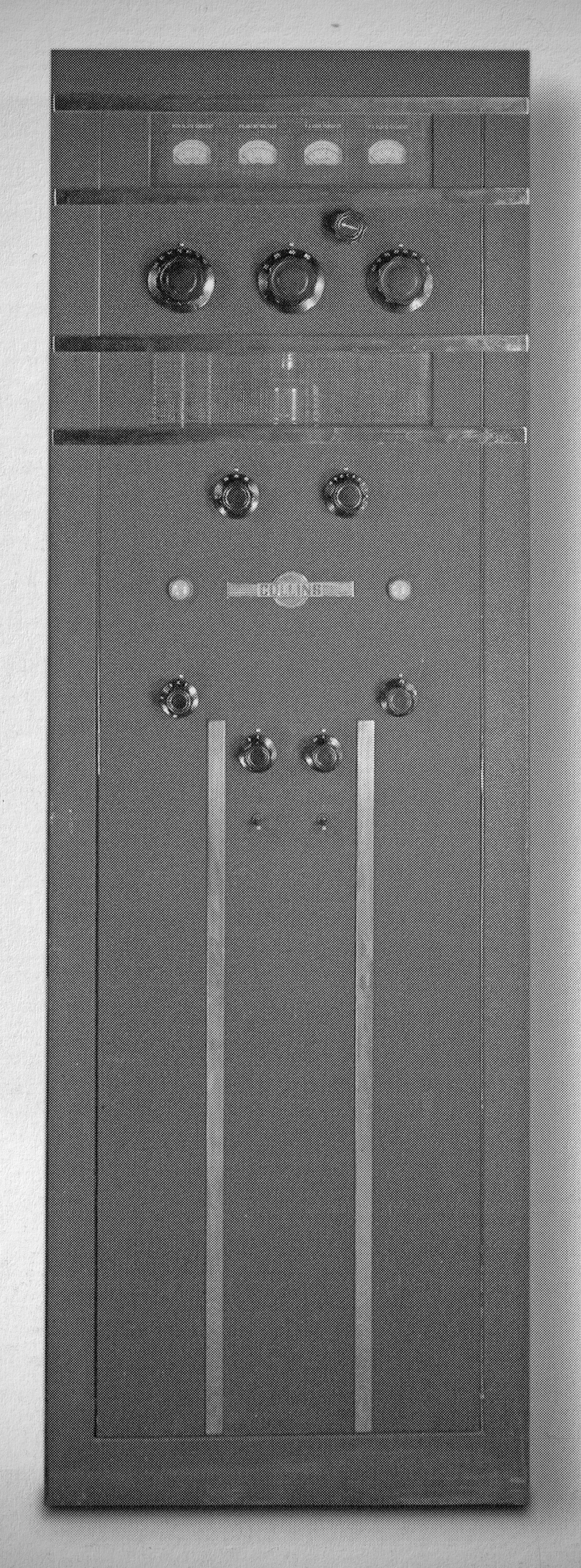
The 30K-1 is a massive, floor-standing transmitter built along the lines of commercial broadcast equipment. It stands 5 feet tall, is finished in a distinctive black wrinkle paint, and weighs over 350 pounds. Its visual aesthetic is pure art deco, featuring prominent vertical and horizontal chrome accent strips, a glass-enclosed meter panel at the very top, and a large viewing window on the front panel to look in on the glowing final amplifier tube.
The 30K-1 is not a standalone unit; it requires an external exciter to drive it. It was originally designed to pair with the matching Collins 310A exciter (a 10-tube unit using a Permeability Tuned Oscillator and dual 807 tubes) and the Collins 75A1 receiver.
Operation requires getting used to a lack of modern push-to-talk capability. Instead of a microphone switch, the operator controls the station using the master mode switch on the 310A exciter, which connects to the 30K-1 via a 5-wire control harness. To operate, the user switches the exciter to "CAL" to zero-beat the receiver, moves it to "REC" to listen, and flips it to "SEND" to mute the 75A1 receiver and key the 30K-1 transmitter into action.
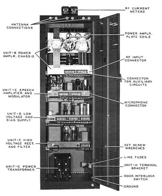
Internally, the transmitter is exceptionally roomy and organized into a vertical stack of four separate, easily removable decks. Each deck connects via a rear terminal strip and is secured by four retaining bolts to support rails, allowing the individual sections to slide straight out for major servicing. From the top down, the cabinet contains:\
– The RF final deck and a front-mounted output network supported by four ceramic standoffs.
– The modulator deck.
– The low-voltage power supply deck.
– The high-voltage power supply deck.
– The heavy Thordarson plate transformer, which sits securely at the very bottom of the cabinet frame.
The transmitter operates on CW and AM Phone (Fone) modes. It is rated for a plate input power of 500 watts on CW and 375 watts on AM, delivering roughly 250 watts of carrier power on AM Phone to provide a full-bodied, punchy, and crisp sound.
The 30K-1 covers the amateur bands from 80 meters down to 10 meters. To span these frequencies, it utilizes a highly flexible, link-coupled output network that allows for both series and parallel tuning. Changing bands requires swapping out a large plug-in coil: one oversized coil handles the lower 80 and 40-meter bands, while a smaller plug-in coil is used for the higher bands. Aside from changing this coil, all operations—including bandswitching, grid tuning, and output matching—are fully controllable from the front panels of the station.
General Features
– Tuning and Control: It features Permeability Tuned Oscillator (PTO) control and is bandswitched across its circuits, with the exception of the antenna tuning network.
– Remote Operation: The exciter unit is housed in a receiver-type cabinet meant to sit directly on the operating desk for convenient, finger-tip remote control.
– Audio Processing: It includes a built-in speech peak clipping circuit that permits a high level of modulation without overmodulating the carrier, followed by a cut-off filter that attenuates frequencies above 4000 cps.
– Antenna Matching: The transmitter incorporates an antenna impedance matching circuit in the output with three pairs of antenna terminals, utilizing a separate plug-in antenna tank with a swinging link.
– Keying and Modulation: It features clean, sharp grid-block keying and supports 100% modulation.
– Metering and Monitoring: The unit is fully metered, tracking modulator plate current, filament voltages, power amplifier grid current, power amplifier plate current, and r-f output.
– Circuit Protection: Primary power circuits are protected by fused primaries, and the power amplifier bias circuit contains a plate power relay that opens if the bias fails.
Tube Lineup
The transmitter utilizes an 11-tube complement and relies on an exceptionally overbuilt, robust circuit design:
– RF Final: The final amplifier stage runs a single 4-125 power tube, visible through the front cabinet window.
– Modulator Section: The modulator deck employs a pair of now-rare 75TH triode tubes, known for their large circular glass globes and bright filaments. The audio section also integrates a 6H6 tube operating as a speech limiter to prevent overmodulation and distortion.
– Power Supplies: The high-voltage deck uses a pair of 866 mercury vapor rectifier tubes alongside heavy, reliable oil-filled capacitors. The low-voltage deck relies on a standard lineup of 5R4GY rectifier tubes to handle bias and low-voltage duties.
1—4-125A r-f power amplifier
1—6SJ7 speech amplifier
1—6SN7 audio amplifier
1—6H6 speech clipper
1—6B4G modulator driver
2—75TH Class B modulators
1—5R4GY bias rectifier
1—5R4GY low voltage rectifier
2—866A high voltage rectifiers
Power requirements
115 VAC, 60 Hz, single phase.
References
Technical description. Radio News, Nov 1946, p. 39.