Note
Shortly after its release in March 1968, Heath began advertising the HW-100 as “the world’s fastest selling transceiver.” Because all those records have been destroyed, we will never know exactly how fast it sold, but it is certain Heath’s claim was no exaggeration. The HW-100 was the right product at the right time for the right price.
Heath initially described the HW-100 as “a five-band version of the single-banders,” (referring the HW-12A, 22A and 32A) explaining that it had “expanded on the single-bander design…” and “borrowed from the heritage of the SB-101.”
Really, the only thing the HW-100 has in common with the single-banders is the design of the front panel. It was much more about borrowing from the SB-101, though “borrowing” probably understates the connection.
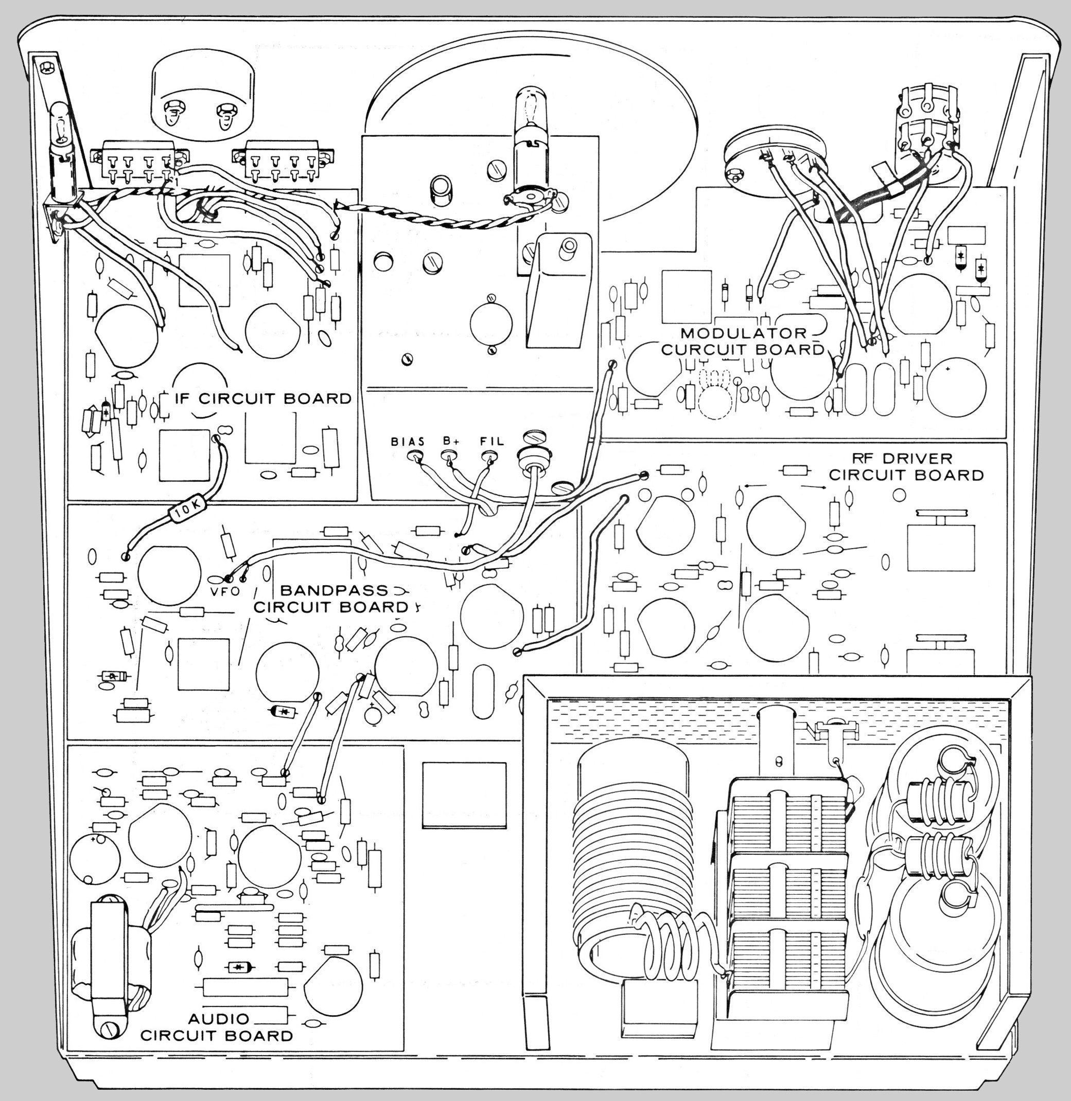
With the exception of the VFO and tuning mechanism, the HW-100 and SB-101 are virtually identical. The SB series uses Heath’s expensive patented Linear Master Oscillator or LMO as it was called, and a specially designed tuning drive mechanism. The HW-100 uses a much simpler and more traditional (but solid state) VFO design, and a different tuning mechanism. The transceiver is built around 19 tubes (including a pair of 6146 finals), five main PC boards, and four small band switch PC boards.
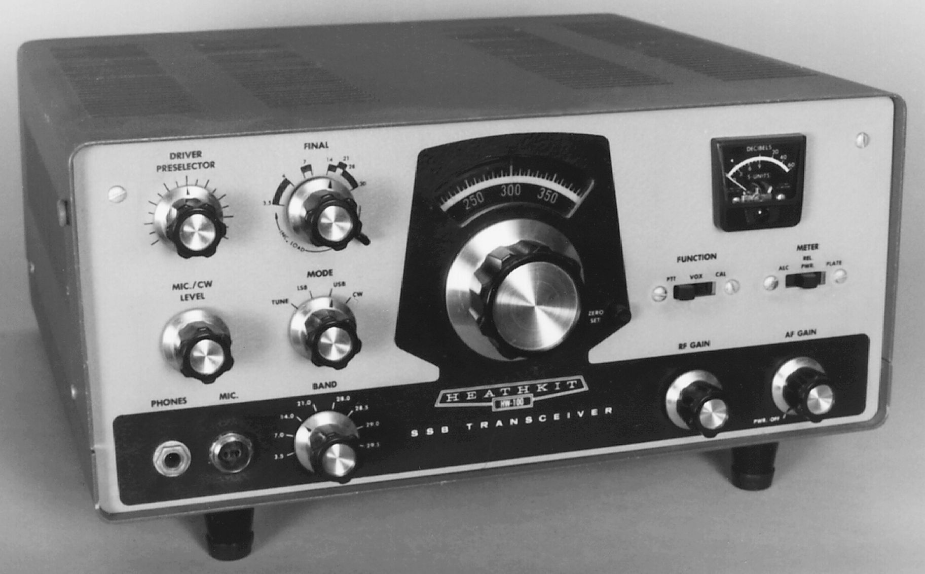
Front panel controls include band and mode selectors, load, final tune, driver preselector, mic/CW level, and slide switches for meter function and PTT / VOX / CAL.
The metal chassis, PC boards, most parts, and parts placement of the HW-100 are identical to those in the SB-101. Even the layout of the front panel is similar. The specifications of the HW-100 are almost identical to the SB-101 as well.
There are provisions for only one filter—SSB. A CW filter was never offered as an option. The HW-100 uses the standard Heath IF frequency of 3395 kHz. Input power is 180 PEP SSB and 170 watts CW. Features include PTT and VOX operation, switch-selectable sidebands, semi-break-in CW (grid block keying) with built-in sidetone, and a built-in 100 kHz crystal calibrator.
The biggest complaint heard about the HW-100 was the tuning dial mechanism. Heath had a patented tuning drive system it called Harmonic Drive. It provided a 28:1 turns ratio to cover 500 kHz. Some users claimed it was full of wobble and backlash. Popular ham magazines published mods to replace the dial with a better one. In the author’s opinion these complaints were overblown. However, the dial is calibrated in 5 kHz divisions, so frequency resolution is very poor.
Rear panel connections include a quarter inch key jack, RCA jacks for ALC input, 8Ω m speaker, and a 50-75Ω antenna. There is also a spare RCA jack. In addition there is an 11-pin power input plug and a ground post. Advertising copy refers to a separate rear panel jack for “RF output” (in addition to an antenna jack), but examples of rigs with this jack have not been found.
There are access holes in the lower right side of the cabinet for screw driver adjustment of controls for meter zero, bias, and VOX. The HW-100 has no internal speaker or power supply and is designed for use with the HP-23 or HP-13 series of power supplies.
The two-tone green styling also incorporates SB series knobs. All things considered, the HW-100 is a fine rig and many are still on the air. Though they are still fairly common, the HW-100 is seen much less often than the HW-101.
HW-100 transceivers have a minor problem with the driver preselector. See SB-100 for details.
Note: Uses the not-quite-as-sharp 404-328 crystal filter. Type 404-283 is a bit sharper and was supplied with the SB-101.
Note: While the assembly manual specifically states that 6146A and 6146B tubes may be directly substituted, experience has shown these tubes can be problematic in operation. Type 6146W should also be avoided.
See HW-101 for additional discussion.
POWER PLUG PINOUTS
1 –130 VDC
2 filament common
3 +300 VDC
4 +800 VDC
5 ground (relay)
6 12.6 volt filament
7 ground
8 nc
9 power switch
10 power switch
11 relay (N.O.)
References:
Review. CQ. Aug 1968, p. 45.
Review. Ham Radio. Sep 1968, p. 64.
Review correction. CQ. Oct 1968, p. 108.
Review. QST. Jan 1969, p. 51.
Dial modification. CQ. Mar 1969, p. 47.
Crystal control. Ham Radio. Jun 1969, p. 36.
RIT (for SB-100). QST. May 1967, p. 49.
RIT. Ham Radio. Aug 1976, p. 81.
RIT. Ham Radio. Jun 1969, p. 67.
RIT. CQ. Jul 1969, p. 86.
Better connection to SB-620. CQ. Feb 1970, p. 89.
Drift and mic gain problems. CQ. Feb 1970, p. 88.
Split frequency operation. CQ. May 1970, p. 32.
Variable AF bandwidth. CQ. Jun 1970, p. 33.
Use with Ameco model PCL RF pre-amp. CQ. Jun 1971, p. 87.
Loose tuning knob. Ham Radio. Jun 1971, p. 68.
Adding a 400 Hz filter. QST. Nov 1971, p. 20.
Improved selectivity. QST. Nov 1971, p. 20.
Increasing capabilities of. CQ. Aug 1972, p. 16.
Grid current monitor. Ham Radio. Feb 1973, p. 46.
Hum fix. CQ. Mar 1973, p. 12.
Deactivated VOX for CW operation. QST. Jan 1974, p. 44.
Offset tuning and keying mods. QST. Mar 1975, p. 19.
Offset tuning and keying mods (more on). QST. Aug 1975, p. 49.
Use with a separate receiver. Ham Radio, Oct 1973, p. 63.
A receiver pre-amp for. CQ. Mar 1976, p. 26.
VFO slippage and backlash. QST. Sep 1976, p. 39.
Digital display for. Ham Radio. Sep 1976, p. 16.
WWV reception. QST. Apr 1969, p. 47.
WWV reception. Ham Radio. Jan 1977, p. 78.
Underrated resistor / CW desense. Ham Radio. Mar 1977, p. 79.
Heterodyne crystal switching. Ham Radio. Mar 1977, p. 78.
Use with low impedance headphones. Ham Radio. Oct 1977, p. 87.
S-meter problem. QST. Apr 1978, p. 40.
Holding the relay. QST. Apr 1979, p. 44.
Sidetone volume control. Ham Radio. Jul 1979, p. 79.
Modification. CQ. Mar 1984, p. 22.
Remote VFO using a salvaged LMO. 73 Amateur Radio. Aug 1984, p. 46.
Change CW offset. 73 Amateur Radio. Mar 1985, p. 48.
Digital frequency display, Ham Radio. Jan 1987, p. 8
Optimizing. QST. Feb 2003.
General information. Electric Radio. Nov 2006.
AM mod. Electric Radio. Dec 2006.
Receiver
Sensitivity: less than 0.5 µV for 10 db signal-plus-noise to noise ratio (SSB)
SSB selectivity: 2.1 kHz minimum @ 6 db down, 7 kHz minimum @ 60 db down
Input impedance: low impedance for unbalanced coaxial input
Output impedance: 8Ω for speaker, high impedance for headphones
Audio power output: 2 watts with less than 10% distortion
Spurious response: image rejection better than 50 db. Internal spurious signals less than 1 µV equivalent
Transmitter
DC power input:
SSB (A3J emission): 180 watts PEP (continuous duty)
RF power output: 100 watts on 80 through 15 meters, 80 watts on 10 meters
Output impedance: 50Ω to 75Ω with less than 2:1 SWR
Oscillator feedthrough or mixer products: 55 db below rated output
Harmonic radiation: 45 db below rated output
T/R operation:
SSB: PTT or VOX
CW: provide by operating VOX from a keyed tone, grid block keying
CW sidetone: approximately 1000 Hz
Microphone requirements: high impedance with ratings of –45 to –55 db
Carrier suppression: 45 db down from single-tone output
Unwanted sideband suppression: 45 db down from single-tone output @ 1000 Hz
Emissions not possible or not recommended: A0, A2, A3b, A4 through A9, F0 through F9, and P0 through P9
Third order distortion: 30 db down from two-tone output
RF compression: 10 db or greater @ 0.1 mA grid current
General
Band coverage: 80, 40, 20 , 15 and 10 meters
Frequency stability: less than 100 Hz per hour drift after 30 minutes warmup, less than 100 Hz for ±10% line voltage variation
Modes: USB, LSB, CW
Dial calibration: 5 kHz divisions
Calibrator: 100 kHz
Bandspread: 28 revolutions for 500 kHz
Audio frequency response: 350 Hz to 2450 Hz
Power requirements:
700 to 850 VDC, 250 mA with 1.0% maximum ripple
300 VDC, 150 mA with 0.05% maximum ripple
–115 VDC, 10 mA with 0.5% maximum ripple*
12 VDC or VAC, 4.75 amps
*Text at the power plug on the rear panel reads “–130 VDC.” Assembly manual diagrams of the rear panel read “–130 VDC.”
Tubes: (1) 0A2, (6) 6AU6, (1) 6BN8, (1) 6CB6, (1) 6CL6, (4) 6EA8,
(1) 6GW8, (2) 12AT7, (1) 12AU7, (2 ) 6146
Photos, general information and specifications from "Heathkit: A Guide to the Amateur Radio Products," by Chuck Penson, WA7ZZE. Used with permission.