Note
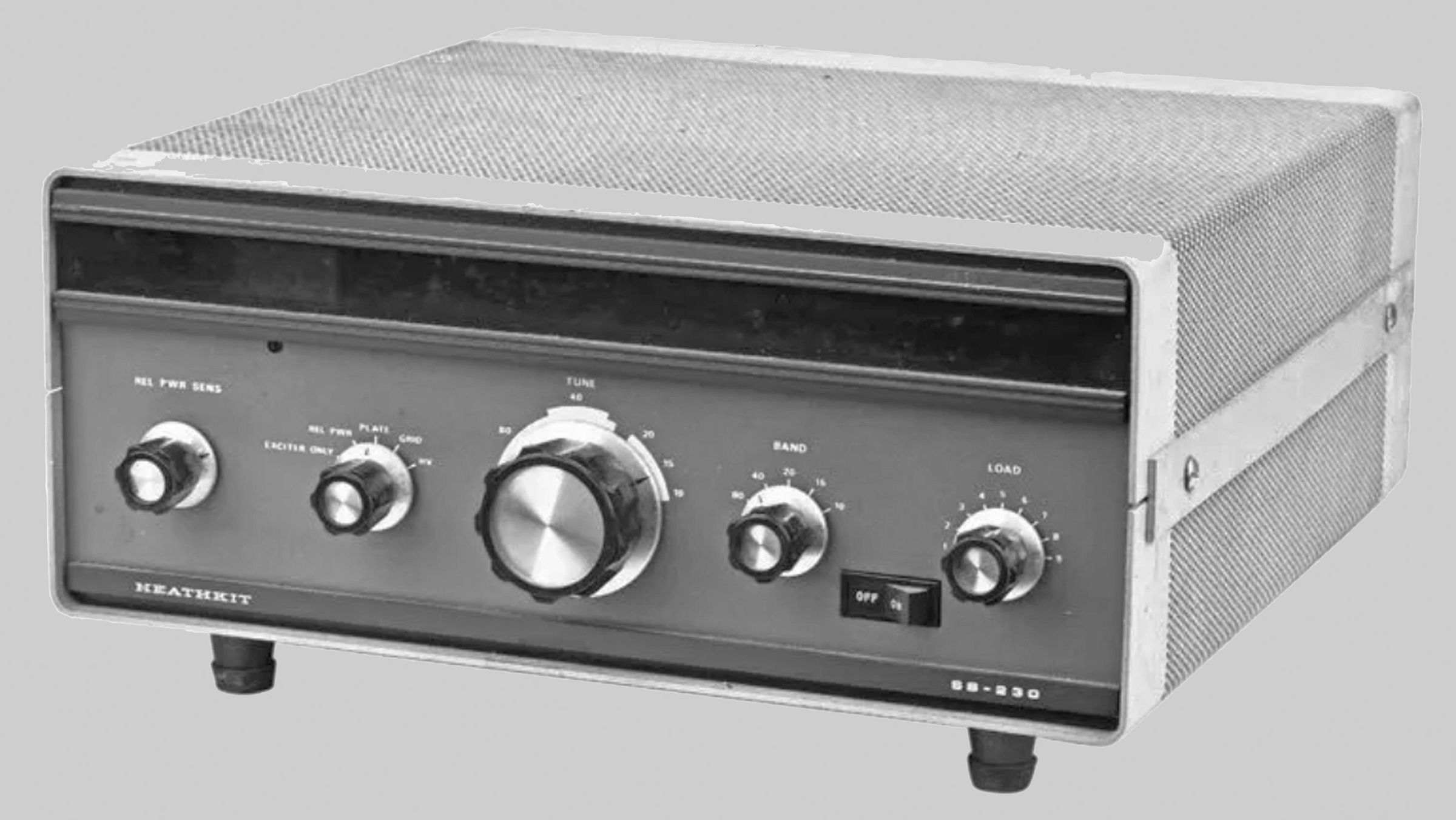
The SB-230 was one of a family of new products released in the Christmas 1974 catalog and is designed to match the SB-104(A) transceiver.
The SB-230 covers 80 through 10 meters and is rated at 1200 watts input PEP and 1000 watts CW, which translates to about 600 watts output or about 400 watts for RTTY or SSTV. It uses a single (and expensive) Eimac 8873 tube, which is convection cooled and operated in grounded grid class B. Convection cooling means the SB-230 requires no fan, and that means very quiet operation.
The amp features a built-in solid-state power supply with a circuit breaker (built into the power switch), safety interlocks, full metering, and ALC connection.
The final tube cathode is fused to protect it from excessive drive. In addition, the amplifier is thermally protected and will shut down if the final tube gets too hot.
An old-technology time delay relay tube provides a 60- to 90-second start-up delay to give the 8873 time to warm up. During this delay the amp cannot be operated, except in the EXCITER ONLY bypass mode.
There is no built-in SWR bridge as in the SB-200.
Front panel controls include a rocker-type power switch, tune, load, and band switch controls, relative power sensitivity, and a combination meter and function control. The illuminated meter reads plate current, grid current, relative power, and high voltage. There are front panel indicators for high temperature, delay mode, and the “exciter only” mode. The “exciter only” mode is essentially a “standby” mode in which the amplifier remains on but is bypassed. This mode is provided since the amp is not an “instant on” type like the SB-200 and 220.
Rear panel connections include a ground post, RCA jacks for antenna relay, ALC and RF input, and an SO-239 for RF output.
The SB-230 is designed for use with 50Ω loads.
The 8873 cathode fuse is also found on the rear panel. It is a 3AG .75 amp fuse.
The SB-230 is a good basic amplifier and will perform well providing it is not pushed too hard. It is well protected from a variety of adverse conditions and is easy to operate.
The SB-230 fell victim to the popularity of Heath’s older SB-201 and 221 amplifiers, which continued to sell well. Poor sales caused Heath to pull the 230 off the market in 1978—several years before the rest of the SB-104 family. No doubt the toxicity of the heat sink (and its potential liability) also played a part in the decision to discontinue the 230.
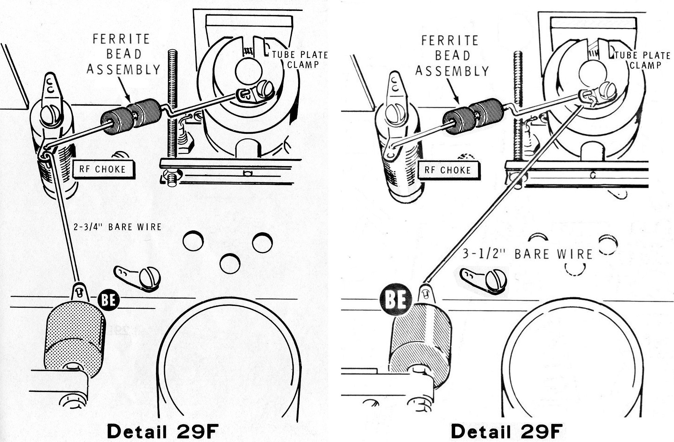
In February 1975, Heath issued a technical exchange bulletin detailing a change in the RF output circuit. Refer to Pictorial C. As originally designed, a pair of ferrite beads was installed between the plate cap of the 8873 and an RF choke in an effort to prevent the choke’s destruction due to VHF oscillations. This design inadvertently placed the beads in the RF output path, creating, in some units, power output instabilities on the higher bands, especially 10 meters.
To fix the instability issue, the bulletin recommended that a wire from the choke to the output capacitor be removed and rerouted from the output capacitor (at point BE), directly to the plate cap of the 8873. This created a separate path for the RF output. This change was implemented in all future production runs. Heath recommended the change for all prior SB-230s.
While the schematic in the assembly manual of the SB-230 was always correct (showing the wiring as in the right-hand version of illustration 29F), the side step-by-step instructions and matching illustration (left-hand version) told a different story. Heath later updated the step-by-step instructions, but neglected to update the illustration, further confusing the issue. By the at least the fourth update of the manual (part number 595-1596-04), illustration 29F had been deleted altogether.
The only real issue with the SB-230 is the high cost of the 8873 tube. If you have to replace it, it will probably cost more than what you paid for the entire amplifier. The SB-230 and the Henry 2K Ultra were the only commercial amateur radio linear amplifiers to use the 8873. There are tubes that are electrically equivalent to the 8873, including the 8874 (3CX400A7), the 8875, and the Russian GI-7B or GI-7BT, but all of these require forced air cooling, which would defeat one of the main selling points of the SB-230—quiet operation.
Caution: Apply only as much drive as required for about 600 watts of output. This will help preserve the life of the 8873.
Danger: The SB-230 contains a block of beryllium oxide. Dust and fumes from this material are DEADLY POISON. The beryllium oxide block is used as part of the heat sink for the 8873 tube and is located in a rear panel cutout between the 8873 and the large finned heat sink on the rear panel. Refer to Pictorials A and B for the location of the beryllium oxide block. DO NOT drill, chip, crush, saw, or file the beryllium block. It should be handled only with protective gloves and eyewear. Also note that the gooey heat sink compound is dangerous. Wash your hands immediately after contact with the beryllium oxide block or the heat sink compound. The beryllium oxide and the heat sink compound should be handled with the utmost care and treated like the hazardous materials they really are.
Warning: In normal operation the temperature of the heat sink may rise to as high as 750 ºF—as hot as the tip of a soldering iron. Keep the amplifier clear of combustible materials and be sure to provide adequate ventilation.
Warning: Lethal voltages present when operating. Interlock switches remove power when the cabinet top or bottom are removed. Defeat them at your peril.
References:
Review. QST. Feb 1976, p. 42.
Review. CQ. Apr 1977, p. 33.
Tuning aid and protective circuits. QST. Jan 1980, p. 51.
TVI. QST. Dec 1985, p. 50.
Band coverage: 80, 40, 20, 15 and 10 meters
Maximum power input:
SSB: 1200 watts PEP
CW: 1000 watts, 50% duty cycle
Duty cycle:
SSB: continious voice modulation
CW: continuous (maximum key down time, 30 seconds)
RTTY/SSTV: 50% maximum transmit time
Drive power required: less than 100 watts
Third order distortion: –30 db or better
Output impedance: 50 to 75Ω at SWR of 2:1 or less
Input: 52Ω at less than 1.5:1 SWR
Zero-signal plate current: 22 mA at approximately 2400 volts
Power requirements:
120 VAC, 50/60 Hz, 14 amps maximum
240 VAC, 50/60 Hz, 7 amps maximum
Tube: (1) 8873
Photos, general information and specifications from "Heathkit: A Guide to the Amateur Radio Products," by Chuck Penson, WA7ZZE. Used with permission.