Note
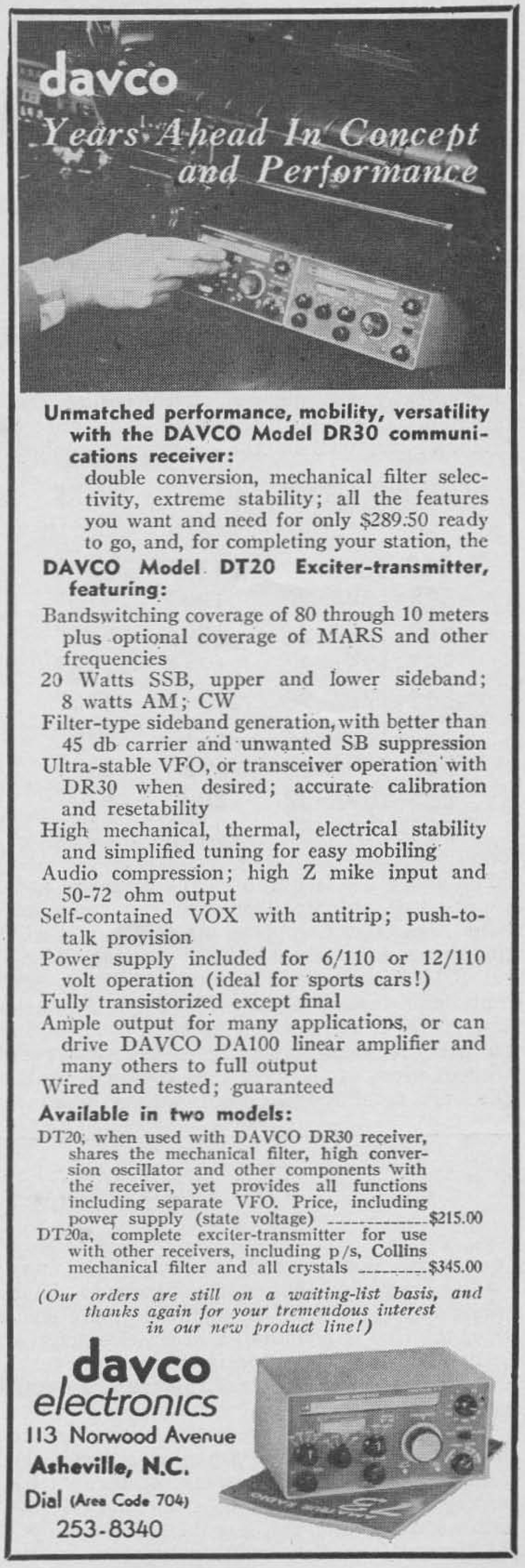
73, Jan 1962, p. 6.
73, Mar 1962, p. 25.
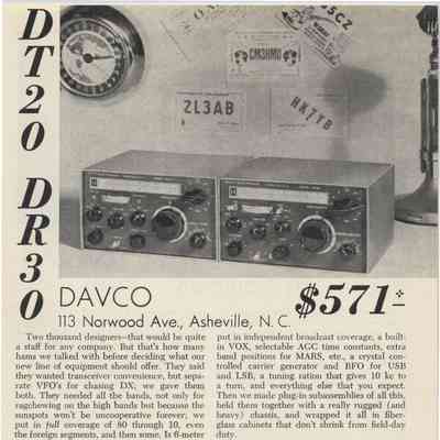
73, Mar 1965, p. 9. ("New!")
73, Jul 1966, p. 23.
QST, Sep 1966, p. 131.
QST, Jan 1967, p. 159.
CQ, May 1967, p. 97. (Specs)
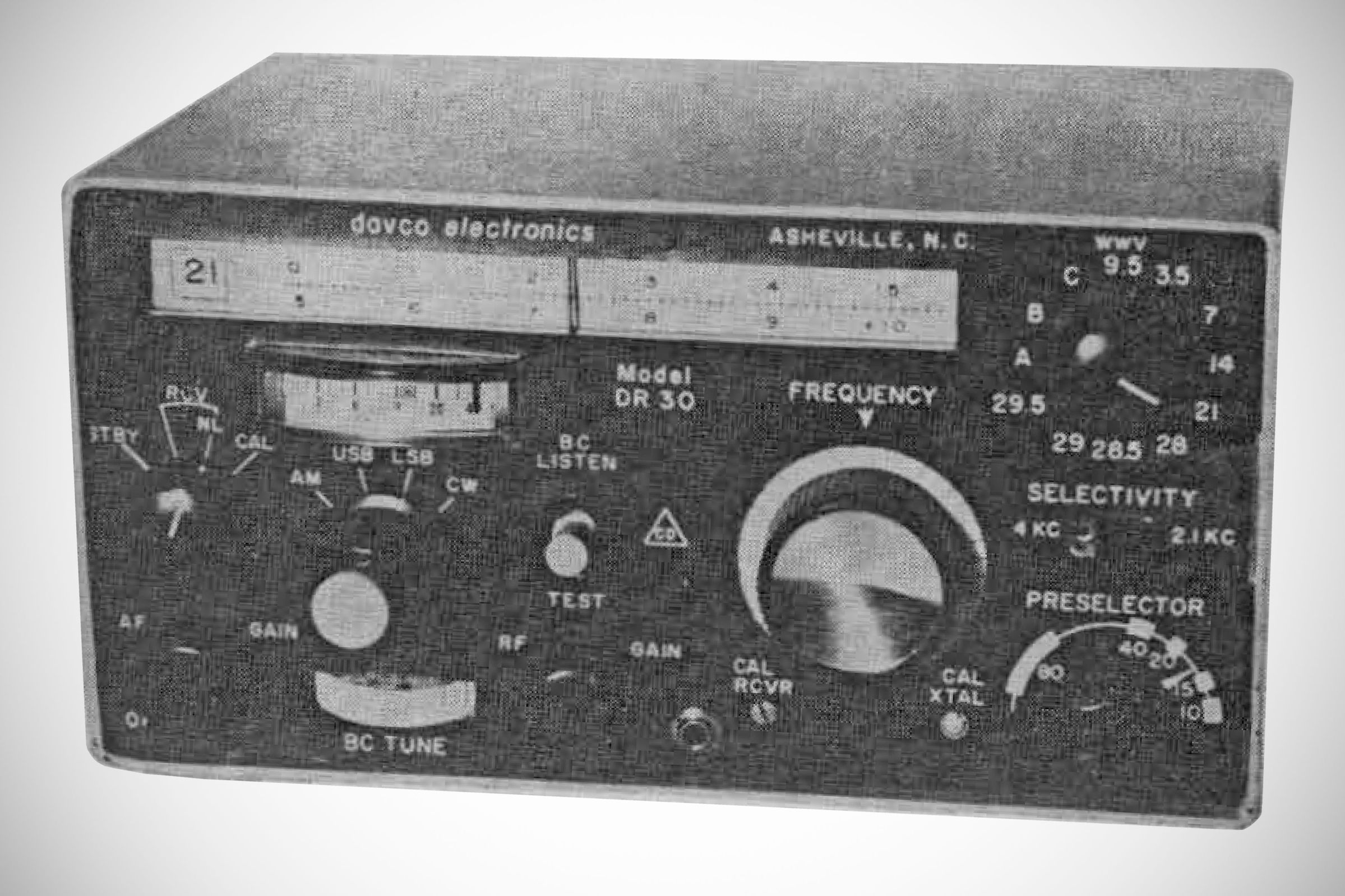
Originally announced late in 1961. A photo of the rig in the first ad looks slightly different than the production model, in a slightly smaller package, and without the 6 meter band.
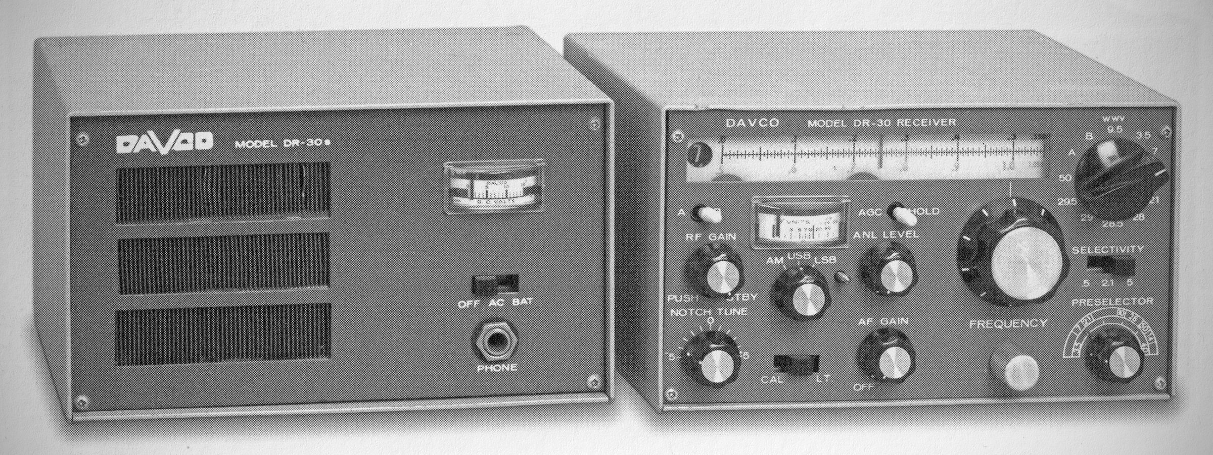
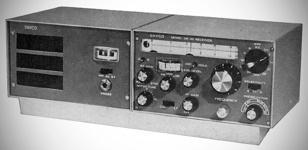
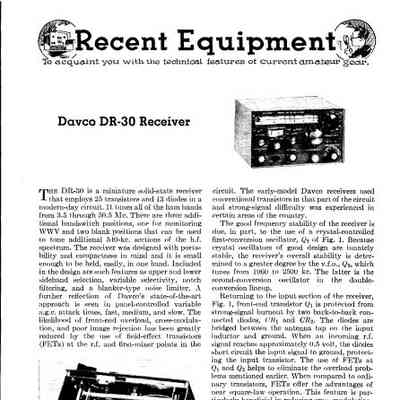
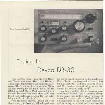
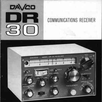
The Davco DR-30 is a compact, high-performance solid-state communications receiver manufactured by Davco Electronics, Inc. of Tallahassee, Florida, designed fixed, mobile, or portable operations.
The DR-30 utilizes a double-conversion superheterodyne design employing 38 solid-state devices. Field-Effect Transistors (FETs) are used in both the RF stage and first mixer, offering high input impedance, superior image rejection, high sensitivity, and resistance to cross-modulation or signal overloading.
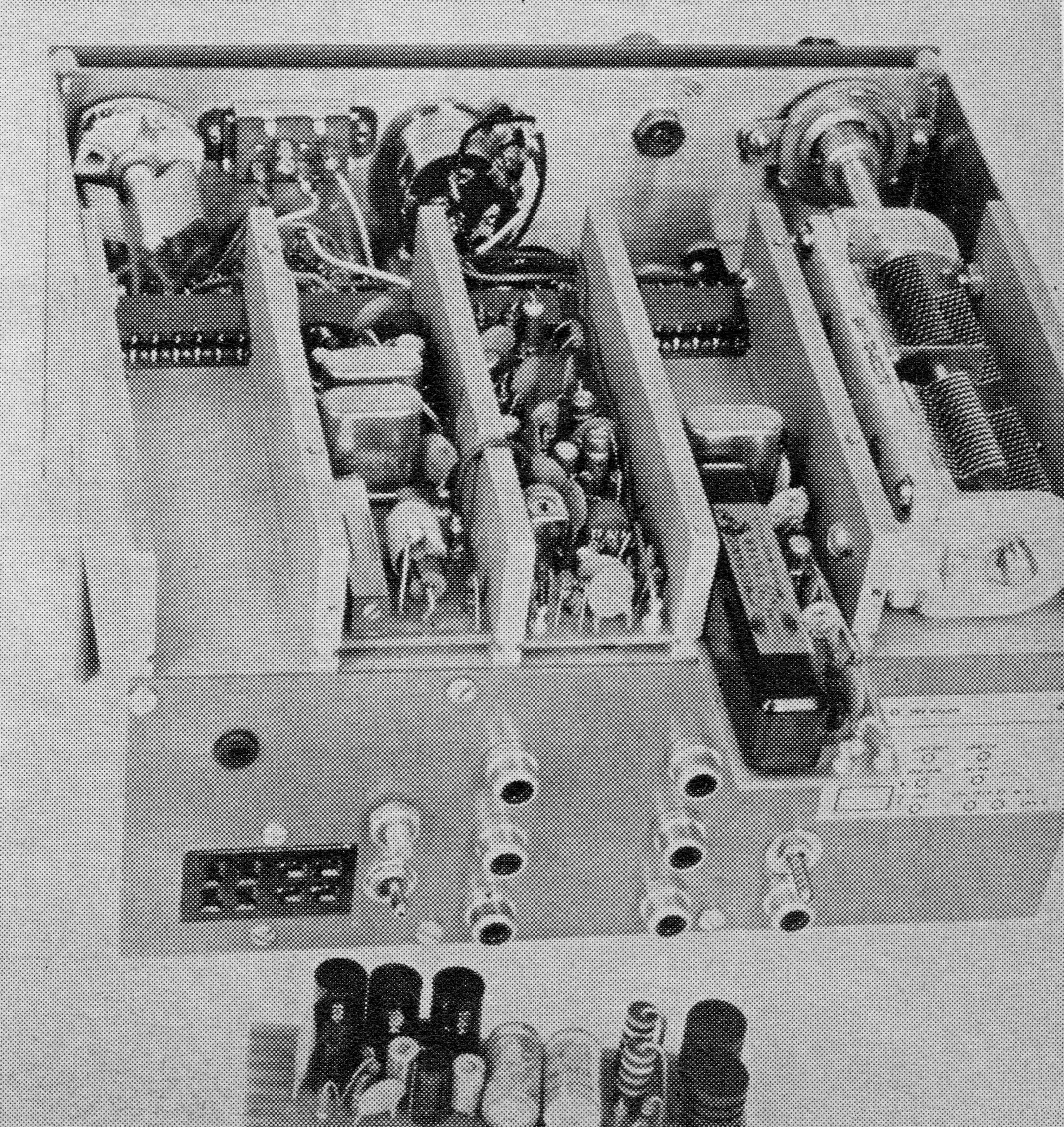
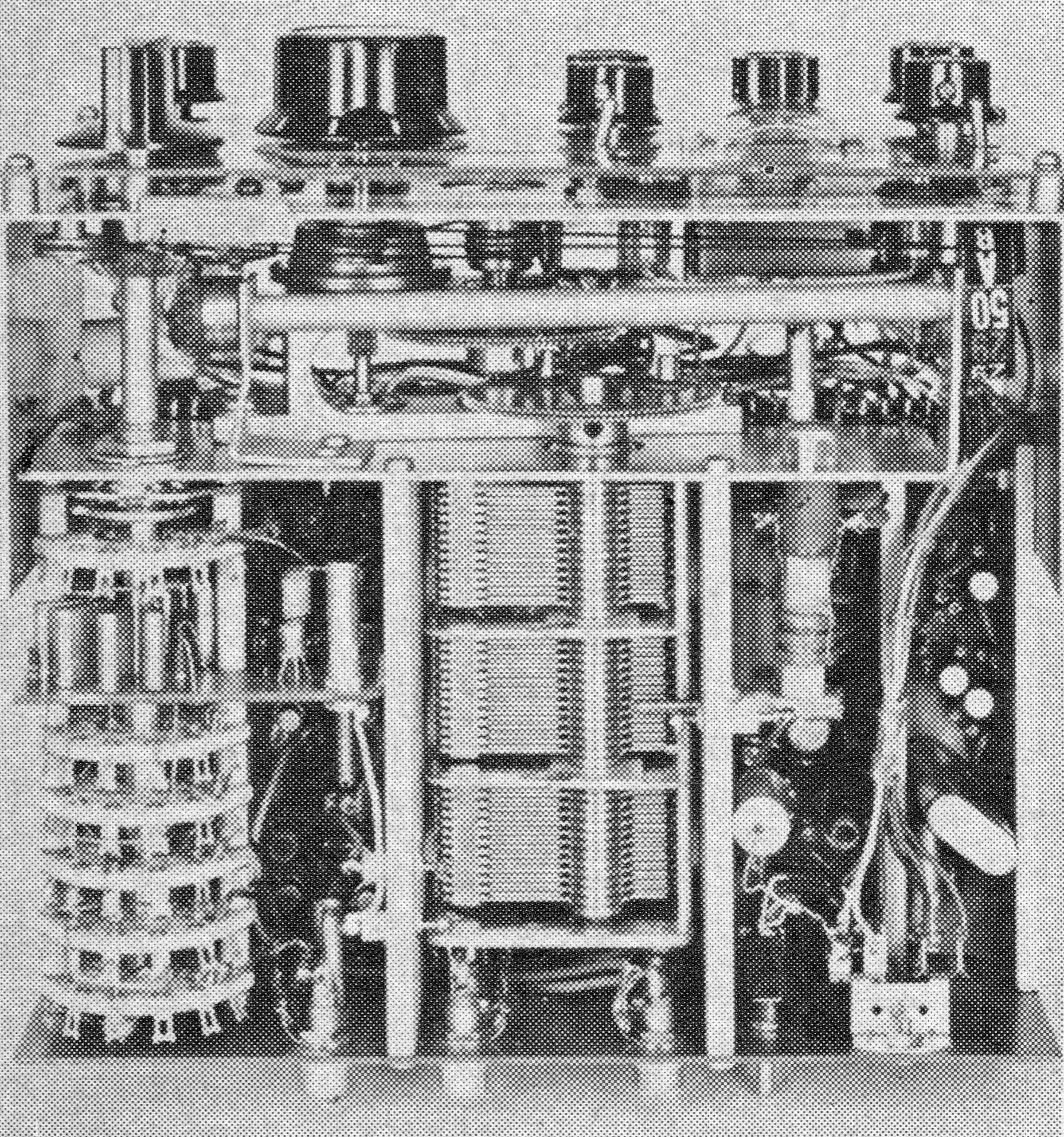
Built with an extruded 3/16" thick aluminum chassis, it features nine modular, glass-epoxy plug-in circuit boards for simplified maintenance. Heat-resistant Teflon-insulated wiring is used throughout.
Frequency Ranges: Covers complete amateur bands from 80 through 10 meters, the first 550 kHz of 6 meters (50--50.55 MHz), WWV/31-meter shortwave (9.5 --10.05 MHz}, and provides auxiliary crystal sockets for two additional 550 kHz segments between 3.5 and 54 MHz.
FET Front End: Field-Effect Transistors (FETs) are used at the RF and first-mixer stages to prevent front-end overload, cross-modulation, and poor image rejection while providing a high signal-to-noise ratio. Diodes protect the RF amplifier from strong-signal burnout.
Double Conversion Circuit: Uses a crystal-controlled first-conversion oscillator and a VFO (1960–2500 kHz) second-conversion oscillator to produce a 455-kHz second IF.
Tuning System: Features a precision VFO utilizing spring-loaded split gears, ball bearings, a dial drag control, and a slide-rule dial with direct frequency readout.
Preselector: Employs a dedicated front-panel preselector to tune high-Q RF circuits across all bands.
Variable Selectivity: Offers diode-switched selectivity options, including a wide IF for AM (5 kHz} bandwidth using ceramic Transfilters, a 2.1 kHz Collins mechanical filter for SSB, and a sharp 500 Hz crystal filter for CW.
Detectors: Includes a linear detector for AM and a product detector with a crystal-controlled BFO/carrier generator for USB/LSB and CW.
Noise Limiter & Rejection: Features an IF-stage blanking-type noise limiter effective against ignition and power-line noise, as well as a tunable IF T-notch filter providing over 50 dB (up to 60 dB} of unwanted carrier rejection.
AGC: Selectable Automatic Gain Control with fast, medium, and slow release settings.
Extras: Includes a built-in 100 kHz crystal calibrator, illuminated dial and S-meter, separate RF/AF gain controls, transmitter muting provisions, rear auxiliary output jacks (VFO, crystals, mechanical filter), and a panel switch for accessory control.
Features
– Covers ham bands 80–6 meters, plus calibrated coverage of any two 500 kHz segments for Citizens' Band, MARS, SWL, etc. with accessory crystals or VHF with converter.
– 9.5–10 MHz. WWV
– Built-in crystal calibrator with front panel correction.
– 50 kHz. overlap eliminates bandswitching in operating DX portion of 10 meters.
– Crystal-controlled and variable BFO for upper and lower sideband and for CW reception.
– Separate diode and product detectors.
– S-meter, AGC; ANL; illuminated dial.
– Fully transistorized.
– Modular construction.
Specifications
– Band Switch: A, B, WWV 9.5, 3.5, 7, 14, 21, 28, 28.5, 29, 29.5, 50
– Modes: AM / USB / LSB / CW
– Selectivity: 5 kHz / 2.1 kHz / 500 Hz
– Sensitivity: better than 1.5 uV
– Double conversion: Crystal-controlled first oscillator; first (variable) IF at 2.5–3.0 MHz.; second IF at 455 kHz.
Power Requirements: Operates directly on 12–15 VDC or via an optional external combination 120 VAC and battery power supply.
– DR30 receiver: Complete with crystals and mechanical filter — $289.50
– DR30a: Same as DR30 but less mechanical filter and BFO-carrier generator crystals. Ideal for most AM use and, with DQ-1, Novice CW — $229.50
– Step-up kit: Converts DR30a to DR30 — $62.00
– DQ-1: Q-multiplier unit. Contains effective Q-multiplier, AC supply for DR30, speaker, battery holder for portable use. Thin-line design, may be permanently attached to receiver or used elsewhere — $36.00
References
Brief description. Electronics World, Nov 1966, p. 103.
Review: CQ, Dec 1966, p. 64.
Brief description. Popular Electronics, Mar 1967, p. 24.
Some backstory:
When Davco Electronics launched the DR-30 in late 1965, they had ambitious plans to offer a complete, ultra-compact station. Early advertising (73, Jan 1961, for example) and period press releases teased a matching system:
The DT-20 transmitter: Planned as a 200-watt SSB/CW companion transmitter designed to match the tiny footprint and style of the DR-30.
The DA-100 matching Linear Amplifier: Intended to provide high-power output for fixed station use while keeping the modular, compact aesthetic of the lineup.
Ultimayly, these products did not make it to production.
Davco was a small, boutique operation founded by Jim Loveless (who named the company after his alma mater, Davidson College) and his father, who handled the mechanical engineering. While the engineering behind the DR-30 was revolutionary—using complex modular sub-assemblies, extruded aluminum frames, and early FET technology—it was also extremely expensive and labor-intensive to manufacture.
The DT-20 transmitter was advertised for sale (see 73 magazine, March 1962, p. 25 for example), but by 1967 or 1968, facing high production costs, a steep retail price tag ($345.50), and limited market adoption compared to established giants like Drake, Collins, and Swan, Davco folded. It is unlikely that the DT-20 was actually sold.
While a few engineering prototypes or mockups of the transmitter may have existed on the workbench in Tallahassee, the DT-20 transmitter and linear amplifier were mostly vaporware.