Note
QST, Oct 1980, p. 103.
QST, Feb 1981, p. 119.
QST, Feb 1982, 99.
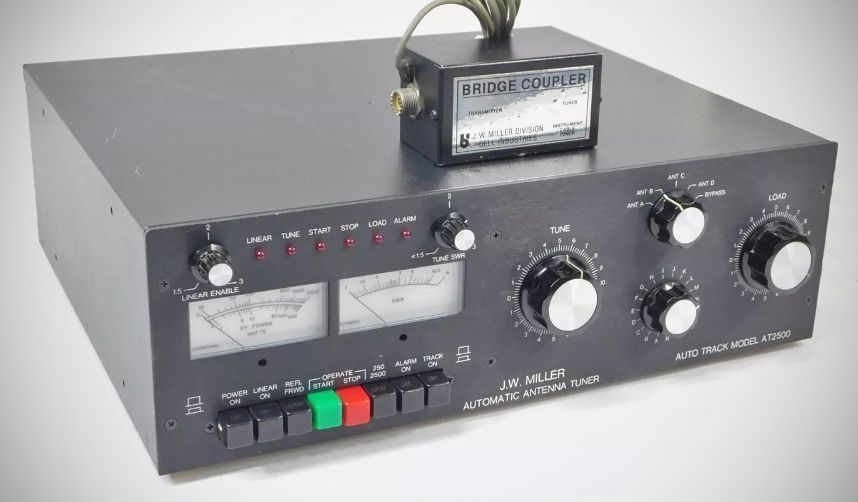
The AT 2500 automatic antenna tuner has been designed to match any transmitter (2500 W max.) to antenna systems using coaxial lines, long wire, or balanced feed lines (with the addition of an external balun).
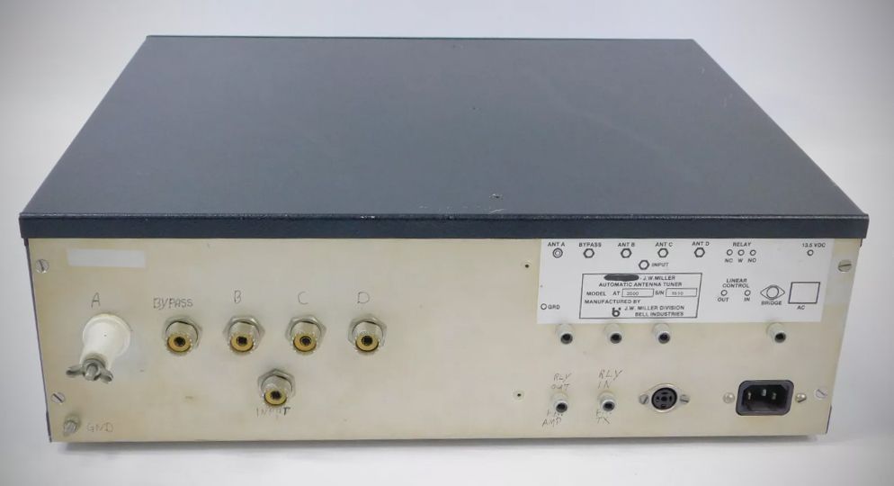
The AT 2500 consists of two main assemblies.
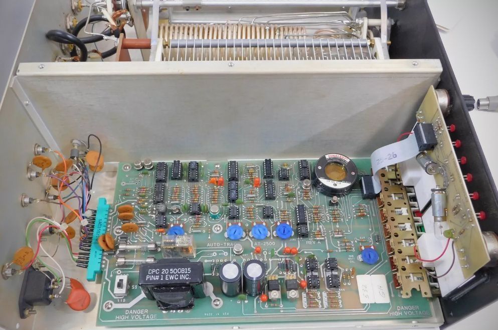
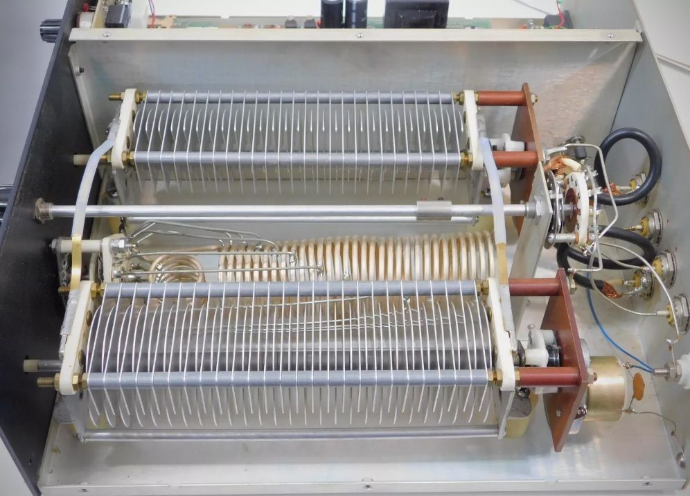
The Main Tuner Assembly houses the high power RF components in the RF compartment on the right side and the two printed circuit boards in the compartment on the left side. These PC boards control the motor-driven high voltage capacitors in the RF compartment.
The tuner portion has been designed so that it can be operated automatically after the band switch has been set, or manually by operating the tune and load capacitor knobs after the automatic feature is switched off. This manual feature makes it possible to operate the tuner in case of failure of the electronic portion of the unit.
Should the electronics package fail, you would still have a manual antenna tuner. However, an external SWR and power meter would be required.
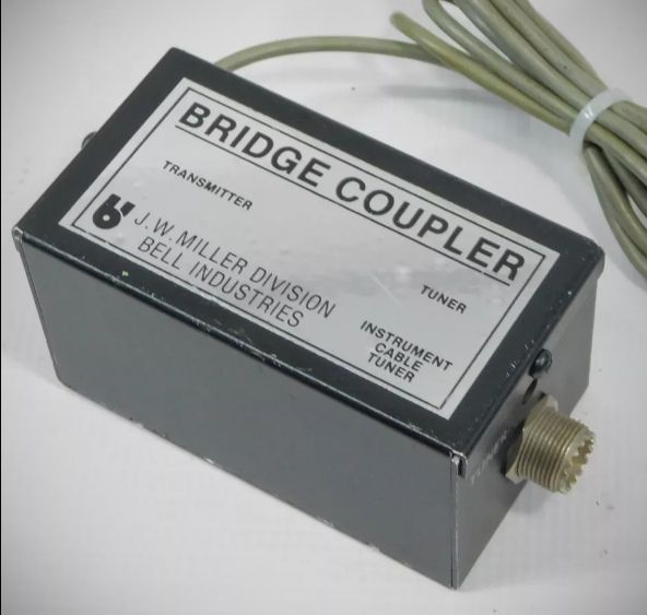
The second assembly consists of a Remote Directional Bridge Coupler which connects to the main tuner assembly via a captive plug-in cable.
Specifications:
– Frequency Range: 3.0 to 30 MHz.
– Power Capability: In excess of 2500 Watts PEP.
– Impedance Matching: 10 to 300 ohms to 50 ohms resistive.
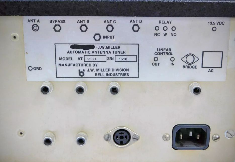
– Outputs: 3 coaxial antennas, 1 long wire, 1 coaxial bypass.
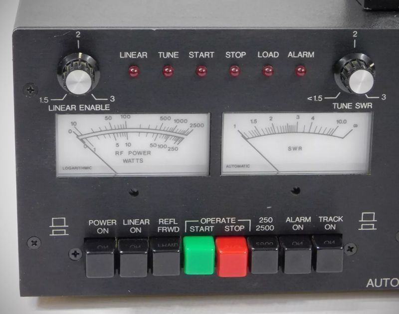
– Power Indication: Illuminated meter with logarithmic scales 0−250 Watts and 0−2500 Watts (push-button select). Continuous carrier RMS, SSB automatic Peak reading.
– SWR Indication: Illuminated meter direct reading SWR 1:1 to ∞.
– Tune-up Time: 15 seconds average.
– Minimum Tune-up Power: 1 Watt.
– Directional Coupler: Toroidal Bridge type. Separate enclosure.
Power Requirements: 115/230 VAC, 50 to 60 Hz, 10 W operating/5 W standby (or) 13.5 VDC, 1 A operating/0.5 W standby.
References
Review. QST, Jul 1981, p. 42.