Note
QST, Sep 1966, p. 127.
QST, Feb 1967, p. 133.
QST, Mar 1969, p. 143.
QST, Nov 1971, p. 160.
QST, Apr 1972, p. 160.
QST, Jun 1973, p. 125.
QST, Jan 1975, p. 103.
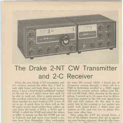
Matches 2-NT transmitter.
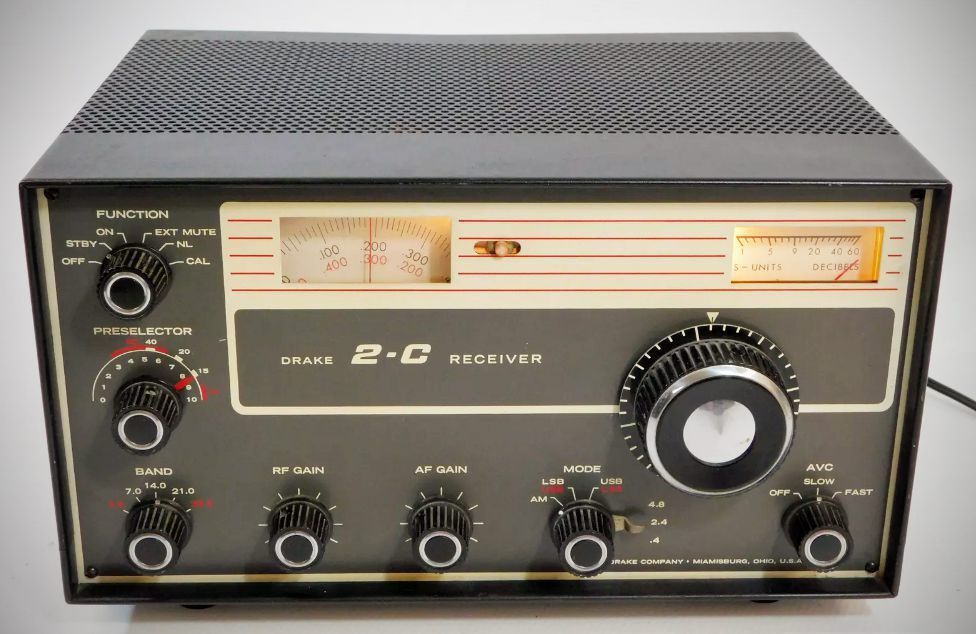
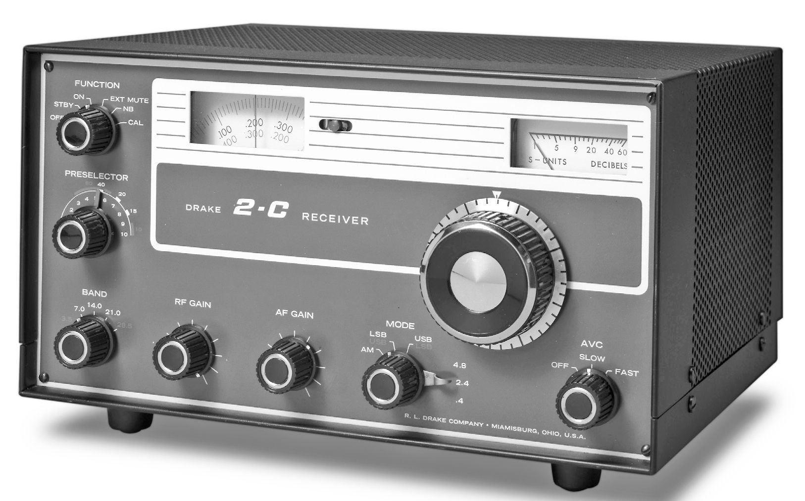
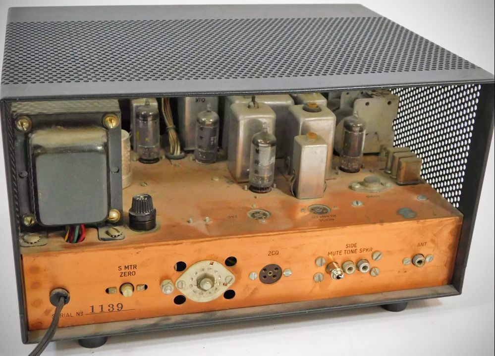
The triple-conversion 2-C gave Drake an entry-level receiver for those not yet ready to step up to the company’s 4-line gear. It was still capable of good performance and was advertised, and often paired, with the 2-NT, a crystal-controlled transmitter of similar appearance. The 2-C covered 80–15 meters and the 28.5–29 MHz portion of 10 meters. Auxiliary crystals permitted the receiver to tune any other 500 kHz range between 3 and 30 MHz. Its 50 kHz IF had .4, 2.4, and 4.8 kHz bandwidths. It used a hybrid mix of five tubes, seven transistors, and three diodes.
Specifications
– Modes of Operation: SSB, CW, AM, RTTY
– Frequency Coverage: 5 standard bands covering the amateur bands:
80M (3.5–4.0 MHz)
40M (7.0–7.5 MHz)
20M (14.0–14.5 MHz)
15M (21.0–21.5 MHz)
10M (28.5–29.0 MHz).
Optional accessory crystals provide 500 kHz incremental coverage for any frequency between 3.0 MHz and 30.0 MHz.
– Selectivity: Selectable passband filter provides three bandwidth options:
0.4 kHz at 6 dB down / 2.7 kHz at 60 dB down
2.4 kHz at 6 dB down / 9.0 kHz at 60 dB down
4.8 kHz at 6 dB down / 16.8 kHz at 60 dB down
(Selectivity switching operates independently of detector and AGC settings)
– Stability: Less than 100 Hz after warmup; less than 100 Hz for a 10% line voltage variation.
– Sensitivity: Less than 0.5 µV for a 10 dB $S+N/N$ ratio on all amateur bands.
– Dial Calibration: Main dial is calibrated 0 to 500 kHz in 10 kHz divisions. Vernier dial is calibrated in approximately 1 kHz divisions. Both dials are adjustable for calibration.
– AGC (Automatic Gain Control): Amplified, delayed AGC featuring selectable slow release (0.75 seconds) or fast release (0.025 seconds) with an attack time under 100 microseconds. Can be turned off manually. Audio output varies less than 6 dB for a 100 dB change in RF input signal.
– Audio Output: 1.8 watts with less than 5% distortion (0.75 watts at AGC threshold).
– Hum Level: Greater than 60 dB below rated audio output.
– Audio Output Impedance: 4 ohms.
– Antenna Input: Nominal 52 ohms unbalanced.
– Spurious Responses: Image rejection greater than 60 dB; IF rejection greater than 60 dB on amateur bands; internal crossover/spurious signals within amateur bands are less than an equivalent 1 µV signal at the antenna.
Tube Lineup (5 total)
– 12BZ6 RF Amplifier
– 12AU6 First Mixer
– 12BE6 VFO-Controlled Second Mixer
– 12BE6 Third Mixer
– 12BA6 50 kHz IF Amplifier
Semiconductors
Q1 (2N3394): Crystal Oscillator
Q2 (1N270 & 2N3394): AM Detector & AM Audio Amplifier
Q3 (2N3394): 50 kHz Oscillator (BFO)
Q4, Q6 (2 x 2N3394): Audio Amplifiers
Q5 (2N3877): AGC Amplifier
Q7 (40310 - RCA): Audio Output
Diodes (2 x 1N270): Product Detector
Rectifiers:
High Voltage Rectifier: Two 1N3194 diodes
Low Voltage Rectifier: Two 1N3194 diodes
Bias Rectifier: One 1N3194 diode
Power Requirements: 120 VAC, 50/60 Hz, 30 watts.
References
Review. 73, Jan 1967, p. 66.