Note
Matches 2-C receiver.
QST, Sep 1966, p. 127.
QST, Mar 1969, p. 143.
QST, Nov 1971, p. 160.
QST, Apr 1972, p. 160.
QST, Jun 1973, p. 125.
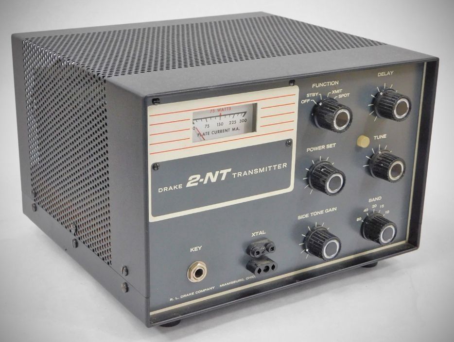
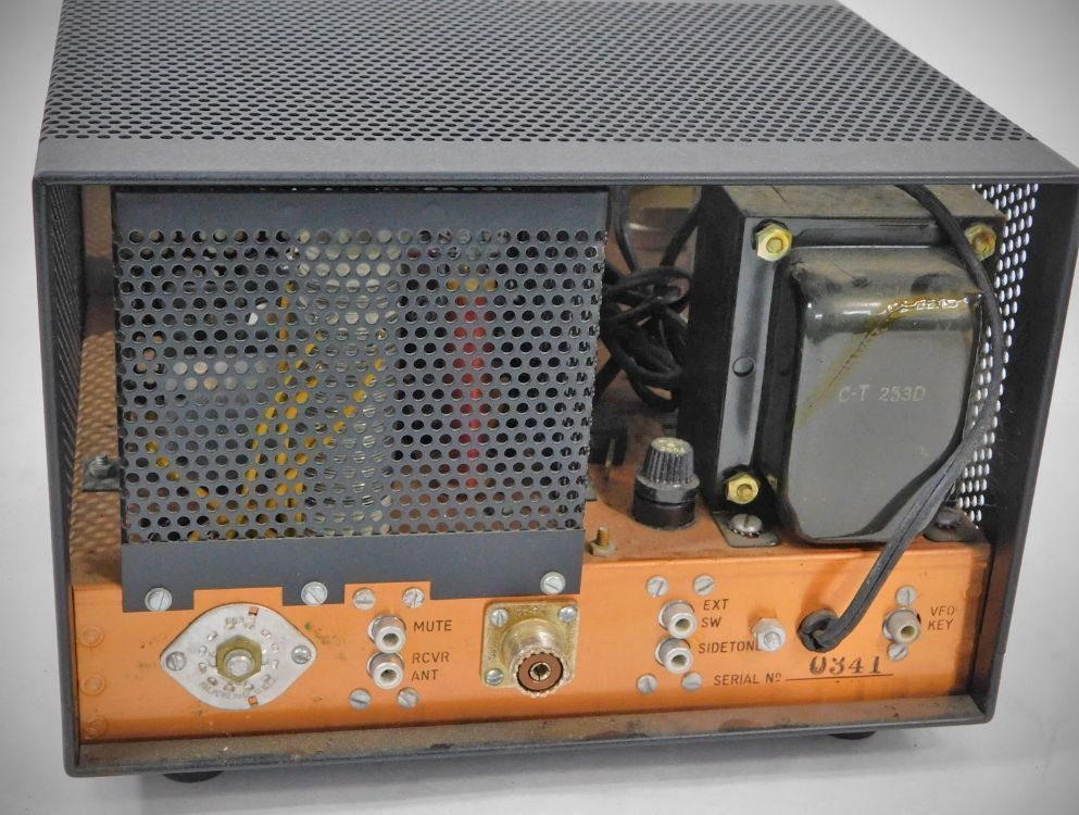
Drake’s crystal-controlled CW transmitter was designed to be paired with the 2-C receiver. Its 100-watt input power could be reduced to meet the 75 watt Novice limit. It had a built-in sidetone oscillator and antenna changeover relay as well as automatic T/R switching. The 2-NT used a 6HF5 final and covered 80–10 meters.
Specifications
– Operating Mode: Break-in CW, Semi Break-in CW, or Manual CW (when used with the Drake 2-C or other receivers).
– Frequency Coverage: Provides crystal-controlled operation in the CW portion of the 80, 40, 20, 15, and 10 meter amateur bands.
– Input Power: Variable up to 100 watts. The plate current meter is red-lined for the 75-watt input power limit required for Novice class operation.
Output Tuning & Filtering: Features a broadband driver stage, a pi-network output with fixed loading, PA plate tuning only, and an integrated low-pass TVI filter to attenuate harmonics.
Control & Keying: Grid block keying, automatic transmit/receive switching via an internal antenna change-over relay, built-in receiver muting, frequency spotting capability, and an integrated sidetone oscillator.
Tube Lineup
– 6EA8 Crystal Oscillator / Relay Control
– 12BY7 Driver amp.
– 6HF5 Final amp
Semiconductors
– Q1 (2N3394): NPN Transistor used in the 900 Hz phase-shift Sidetone Oscillator.
– D1, D2, D10 (1N483A): Silicon Diodes used in the keying pulse forming, delay, and relay control circuits.
– D3 (1N483A): Silicon Diode used as the sidetone oscillator control switch.
– D4 through D9 (1N3194): Silicon Diodes serving as rectifiers for the high-voltage B+, screen, and negative bias supply circuits.
Power Requirements: 120 VAC, 50/60 Hz, 2.8 amperes.
References
Review. 73, Jan 1967, p. 66.