Note
QST, Jun 1966, p. 125.
QST, Jan 1967, p. 123.
QST, Jan 1968, p. 119. (L-4B, Intro date is late 1967. More power, new tubes.
QST, Feb 1971, p. 150.
QST, Nov 1971, p. 160.
QST, Jun 1973, p. 125.
QST, Jun 1975, p. 133.
QST, Apr 1976, p. 81.
QST, Dec 1977, p. 152.
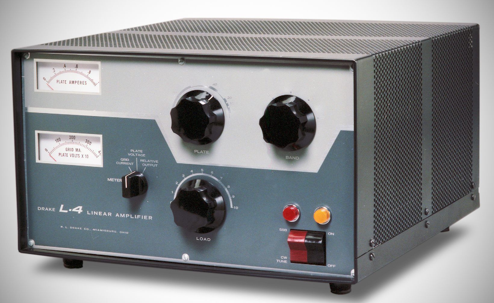
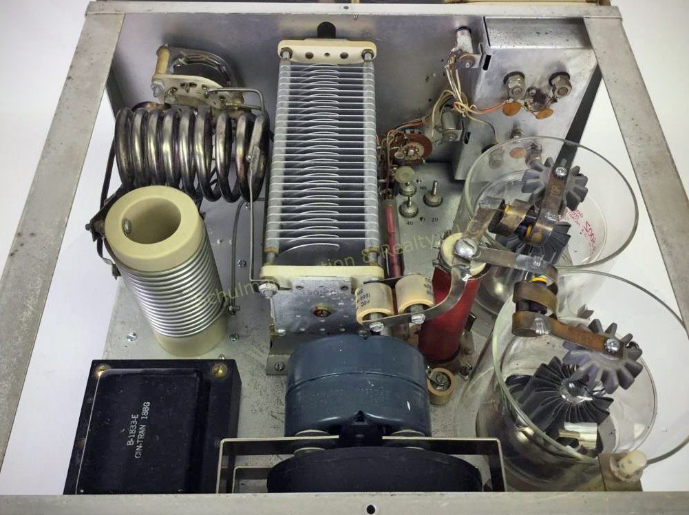
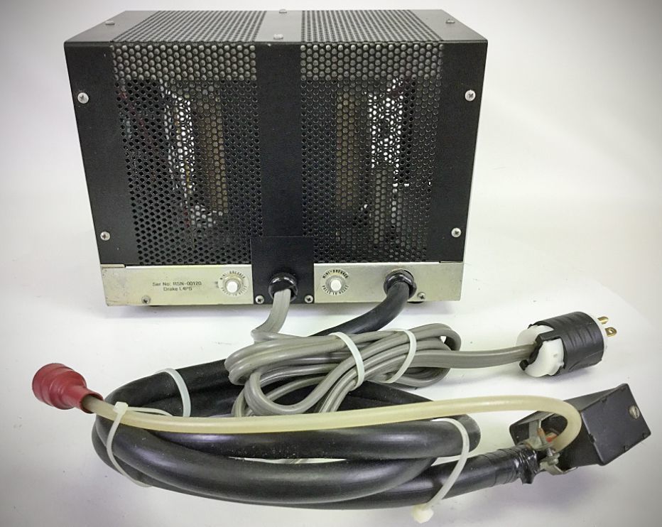
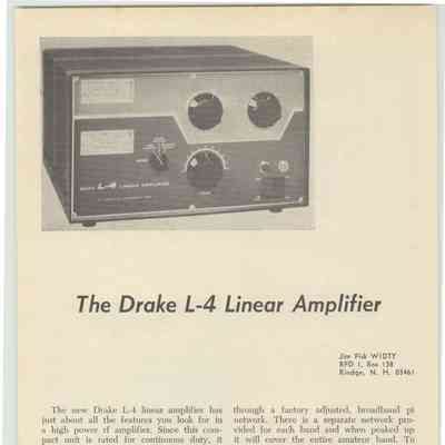
The Class B grounded-grid L-4 ran 2000 watts PEP SSB and1000 watts DC input on CW, AM, and RTTY. Drake’s amp used a pair of 3-400Z or 8163 tubes. Quick-heating filaments allowed the amplifier to remain off until needed. A warmup of only 3 seconds was required. The L-4 covered 80–10 meters. Its solid-state power supply was on a separate chassis.
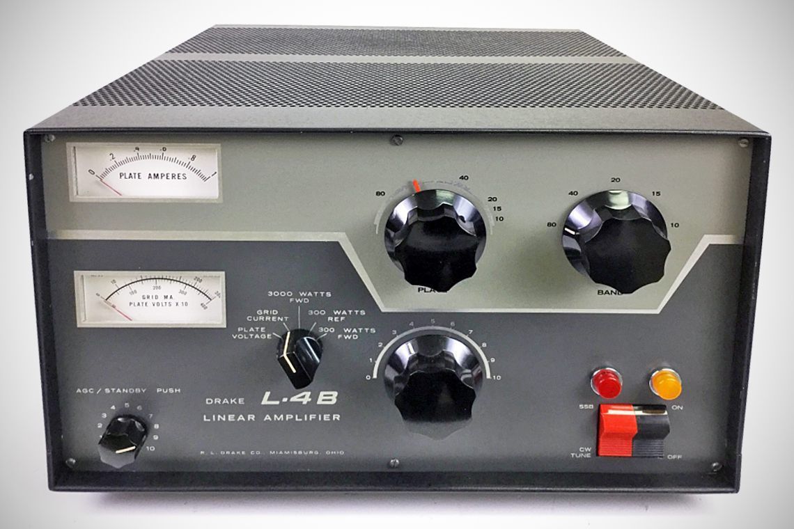
The main differences between the Drake L-4 and the upgraded Drake L-4B HF linear amplifiers fall into three primary areas:
1. Tubes
Drake L-4: Factory-equipped with a pair of 3-400Z power triode tubes.
Drake L-4B: Upgraded to use a pair of 3-500Z tubes (offering slightly higher dissipation head-room), though a small number of very early L-4B units shipped with 3-400Zs before the transition was complete.
2. Metering and Power Measurement
Drake L-4: Included a relative RF power output meter.
Drake L-4B: Replaced the relative meter with a calibrated Bruene-style directional wattmeter, allowing direct measurement of forward power (300 W and 3000 W full-scale ranges) and reflected power (300 W range).
3. Front Panel Controls (ALC & Standby)
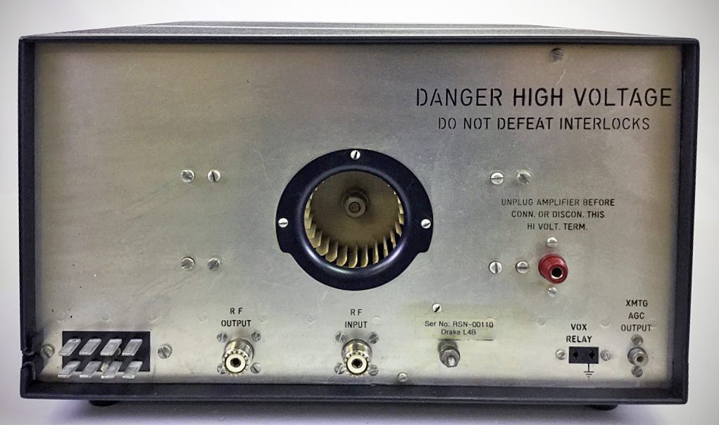
Drake L-4: The ALC adjustment potentiometer was located on the rear chassis apron. There was no built-in front-panel Standby switch.
Drake L-4B: Moved the AGC/ALC threshold control to the lower-left corner of the front panel and incorporated a push-pull switch into the knob to switch between Operate and Standby modes.
Despite these operational refinements, both amplifiers share the same general specifications.
Specifications
– Frequency Coverage: Ham bands 80 through 10 meters. All frequencies 3.5 to 30 MHz may be covered with some retuning of input coils.
– Plate Input: 2000 watts PEP SSB; 1000 watts DC on CW, AM, and RTTY.
– Drive Requirements: 100 watts PEP SSB; 75 watts CW, AM, and RTTY.
– Input Impedance: 50 ohms.
– Output Impedance: Adjustable pi-network matches 50 ohm line with SWR not to exceed 2:1.
Power Requirements:
230 VAC, 50/60 Hz, 15 amps
115 VAC, 50/60 Hz, 30 amps
Power Supply: 6 3/4 W x 7 7/8 H x 11 D, 43 lbs
References
Review. 73, Feb 1967, p . 90.