Note
CQ, Jun 1964, p. 9.
QST, Jan 1965, p. 99.
QST, Feb 1965, p. 133. (full specs)
QST, Dec 1965, p. 139. (R-4A)
73, Apr 1967, p. 25.
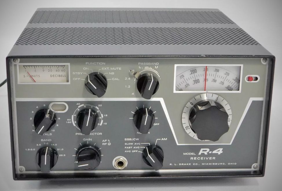
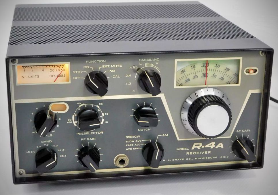
Drake's R-4 receiver tuned fifteen 500 kHz ranges between 1.5-30 MHz (with the exception of 5 to 6 MHz) and was supplied with crystals for 80, 40, 20, 15 meters, and 28.5-29 MHz on 10 meters. The crystal switch had 1 0 spare positions for optional crystals. Its linear PTO had 1 kHz dial divisions. The double-conversion receiver had a first IF at 5645 kHz with a crystal lattice filter and a 50 kHz 2nd IF with UC filtering. Its passband tuning offered bandwidths of 0.4, 1.2, 2.4, and 4.8 kHz. The R-4 used 13 tubes and 7 diodes. It had a noise blanker, notch filter, and crystal calibrator.
The Drake R-4A was similar in concept and appearance to the R-4, with some internal circuit changes, including a solid-state PTO. It was manufactured in both 11 and 13 tube versions.
The series continued with the R-4B and R-4C. See separate entries for each.
Features (Model R-4)
– Linear permeability tuned VFO with 1 KHz dial divisions.
– Covers ham bands 80, 40, 20, 15 meters completely and 28.5 to 29.0 MHz of 10 meters with crystals furnished.
– Also covers 160 meters, Mars, Citizens Band, WWV, Marine, and short wave broadcasts. (With accessory crystals.)
– Or will give 5 MHz of continuous coverage (with accessory crystals) for use with VHF converters.
– Or tunes any ten 500 KHz ranges between 1.5 MHz and 30 MHz with accessory crystals; 5.0 to 6.0 MHz not recommended).
– Passband tuning
– Noise blanker that works on CW, SSB, and AM; Notch filter; and 100 KHz crystal calibrator are built in.
– Crystal lattice filter 1st IF
– Premixed injection - Crystal oscillator and low frequency VFO outputs premixed.
– AVC with fast attack and slow release for SSB or fast release for high speed break-in CW. Also AVC may be switched off.
– Receives SSB, AM, CW, and RTTY with full RF gain, complete AVC action and accurate S-meter indication.
– Product detector for SSB/CW-diode detector for AM.
– Transceive capability; May be used to transceive with the T-4 "Reciter" or T-4X Transmitter.
Specifications (Model R-4)
– Frequency Coverage: 3.5-4.0 MHz, 7.0-7.5 MHz, 14.0-14.5, 21.0-21.5, and 28.5-29.0 MHz with crystals supplied. Ten accessory crystal sockets are provided for coverage of any 10 additional 500 kHz ranges between 1.5 and 30 MHz with the exception of 5.0-6.0 MHz.
– Selectivity: Drake tunable passband filter provides:
0.4 KHz at 6 DB down and 2.6 kHz at 60 DB down
1.2 KHz at 6 DB down and 4.8 kHz at 60 DB down
2.4 KHz at 6 DB down and 8.2 kHz at 60 DB down
4.8 KHz at 6 DB down and 25 kHz at 60 DB down
Note: Selectivity switching is independent of detector and AVC switching.
– IF: First IF 5645 kHz crystal lattice filter; second IF 50 kHz tunable L/C filter.
– Stability: Less than 100 Hz after warm up. Less than 100 Hz for 10% line voltage change.
– Sensitivity: Better than 0.5 uV for 10 DB signal plus noise to noise on all amateur bands.
– Modes: SSB, CW, AM, RTTY.
– Dial Calibration: Main dial calibrated 0 to 500 kHz and 500 to 1000 kHz in 5 KHz divisions. Vernier dial calibrated 0 to 25 kHz in 1 kHz divisions.
– Calibration: Better than 1 KHz when calibrated at nearest 100 kHz point.
– AVC: Amplified delayed AVC having slow (.75 sec.) or fast (.025 sec.) discharge; less than 100 microsecond charge. AVC can also be switched off. 3 DB change in AF output with 60 DB change in RF input.
– Audio Output: 1.4 watts max. and .5 watts at AVC threshold.
– Audio Output Impedance: 4 Ohms and hi impedance for anti-vox.
– Antenna Input: Nominal 52 Ohms.
– Spurious Response: Image rejection more than 60 DB. I.F. rejection more than 60 DB on ham ranges. Internal spurious responses in ham ranges less than the equivalent 1 uv signal on the antenna.
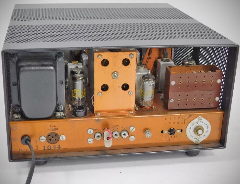
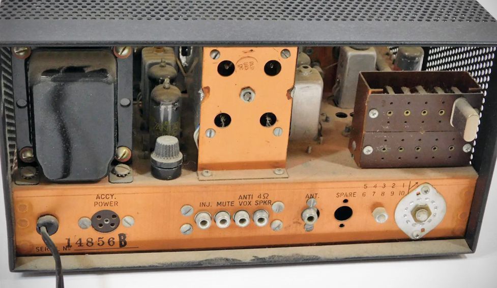
Rear Chassis: S-meter zero, notch adjust, antenna jack, speaker jack, mute jack, anti-vox jack, accessory power socket, and fuse post.
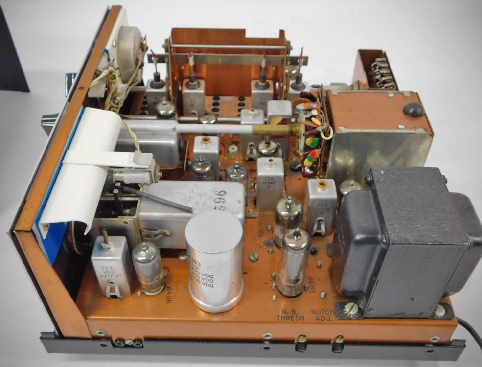
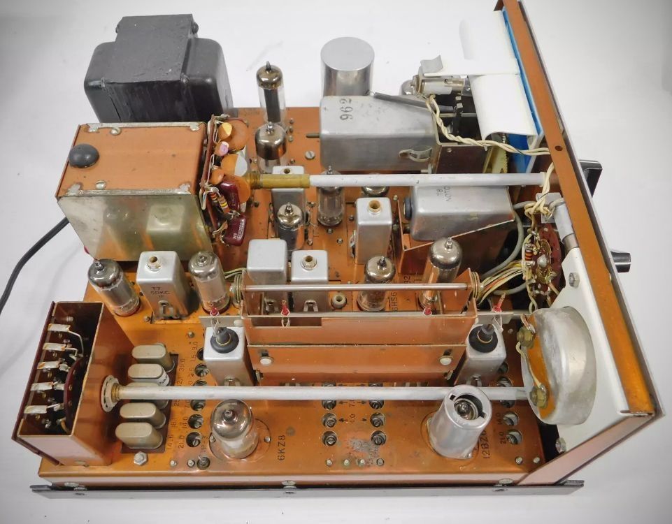
Tube Lineup (Model R-4) (13 total)
– 12BZ6: RF amplifier
– 12BZ6: 100 KC calibrator
– 6HS6: 1st mixer
– 6AU6: PTO (Permeability Tuned Oscillator)
– 6KZ8: Premixer / xtal oscillator
– 12BE6: 2nd mixer and xtal oscillator
– 12BA6: 50 KC IF
– 12BA6: 50 KC IF
– 12AV6: AVC amplifier / AVC detector
– 6GX6: Product detector / audio amplifier
– 6EH5: Audio output
– 12BA6: Noise blanker amplifier
– 12AX7: Noise blanker pulse amplifier / shaper
– Tube Lineup (R-4A) (11 total)
– 12BZ6: R.F. amp.
– 12BA6: 100 KC calibrator
– 6HS6: 1st mixer
– 6HS6: Premixer
– 12BE6: 2nd mixer and xtal oscillator
– 12BA6: 50 KC I.F.
– 12BA6: 50 KC I.F.
– 6EH5: Audio output
– 12BA6: Noise blanker amp.
– 12AX7A: Noise blanker amp./shaper
– OB2: Voltage regulator
Power Requirements: 120/240 VAC, 50/60 Hz, 50 watts
Accessory: Model MS-4 matching speaker cabinet with high efficiency 5 x 7 speaker. Cabinet also houses the power supply for the T-4 or T-4X matching transmitters.
References
Review (R-4). 73, Jan 1966, p. 78.
Review (R-4A). 73, Jan 1969, p. 76.
Improving (R-4A). 73, Jan 1973, p. 112.