Note
QST, Dec 1967, p. 127. (R-4B)
QST, Mar 1973, p. 119. (R-4C)
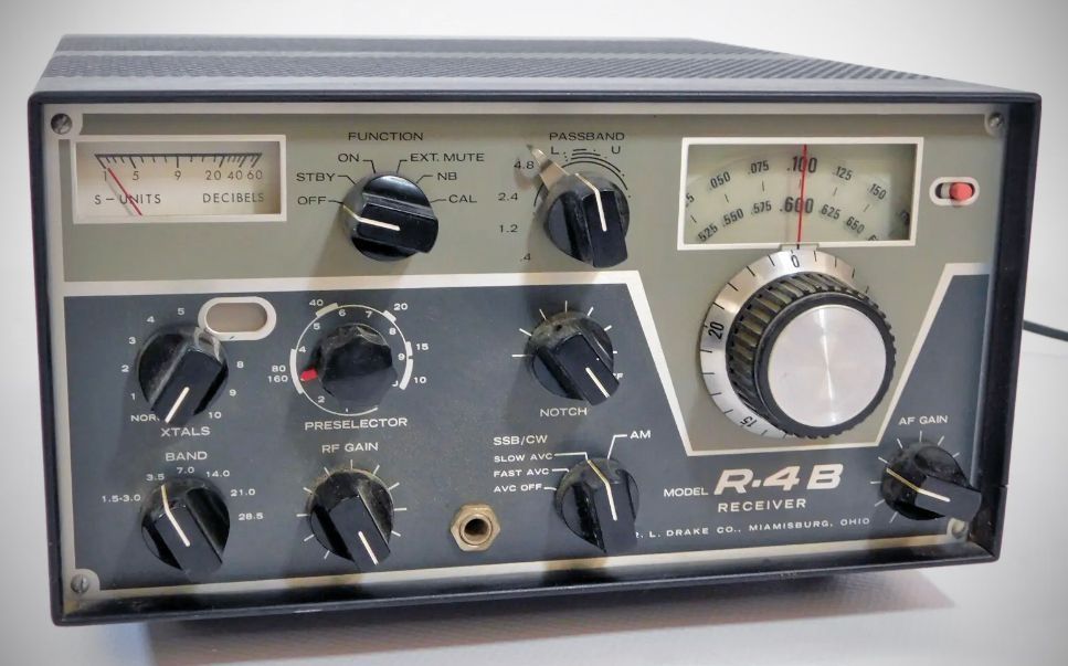
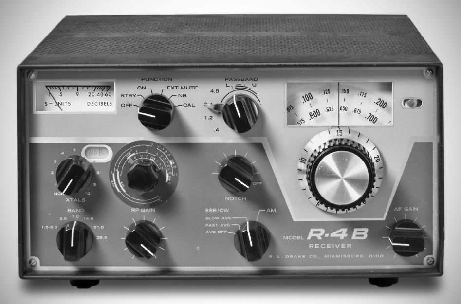
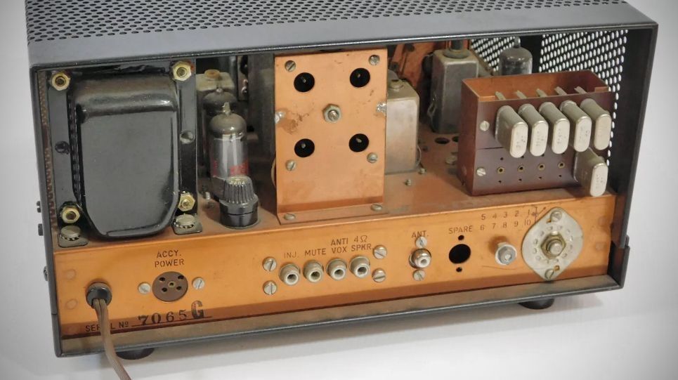
The R-4B continued with the same basic setup of earlier R-4 receivers, but made increasing use of solid-state technology with 9 tubes, 10 transistors, 17 diodes, and 2 ICs. Solid-state devices were used in the PTO, crystal oscillator, AVC, BFO, crystal calibrator, and audio amplifier. There was a new tuning knob as well as cosmetic front-panel differences.
Specifications
– Frequency Coverage: Covers 3.5 to 4.0 MHz, 7.0 to 7.5 MHz, 14.0 to 14.5 MHz, 21.0 to 21.5 MHz, and 28.5 to 29.0 MHz.
– Accessory Coverage: Ten accessory crystal sockets are provided. Coverage of any ten additional 500 kHz ranges between 1.5 and 30 MHz (except between 5.0 and 6.0 MHz) can be added by installing accessory crystals.
– Selectivity: The R-4B tunable passband filter provides four passbands.
Set to 0.4, the bandwidth is 0.4 kHz at 6 dB down and 2.6 kHz at 60 dB down.
Set at 1.2, bandwidth is 1.2 kHz at 6 dB down and 4.8 kHz at 60 dB down.
Set at 2.4, bandwidth is 2.4 kHz at 6 dB down and 8.2 kHz at 60 dB down.
Set at 4.8 kHz, bandwidth is 4.8 kHz at 6 dB down and 20 kHz at 60 dB down.
– Selectivity switching is independent of detector and AVC switching.
– Intermediate Frequencies: First is 5645 kHz with crystal lattice filter; second is 50 KHz with tunable LC filter.
– Stability: After warm up, frequency will not drift more than 100 Hertz. Line voltage variation of 10% will not cause frequency shift in excess of 100 Hertz.
– Sensitivity: 10 dB signal-plus-noise to noise ratio obtained on any amateur band with less than 0.5 microvolt signal on the antenna.
– Modes of Operation: SSB, CW, AM, RTTY.
– Spurious Responses: Image rejection over 60 dB. I.F. rejection over 60 dB on amateur bands. Internal spurious response less than the equivalent of a 1 microvolt antenna signal on all amateur bands.
– AVC: Amplified-delayed AVC with slow (750 milliseconds) or fast (25 milliseconds) discharge, and less than 100 microseconds charge time. A 60 dB change in R.F. input causes less than 3 dB change in audio output.
– Input Impedance: 52 ohms nominal.
– Output Impedance: 4 ohms to speaker, 600 ohms to headphones, 5000 ohms anti-vox.
– Audio Output: 0.5 watt at AVC threshold, 1.5 watts maximum.
– Calibration: Better than ±1 kHz when calibrated at nearest 100 kHz calibration point.
– Hum & Noise: Greater than 60 dB below rated output.
Tube Lineup (9 total)
Note: While the tubes are numbered V1–V10, V6 is not used,
– 6BZ6 – R.F. Amplifier
– 6HS6 – First Mixer
– 12BE6 – Second mixer and crystal oscillator
– 12BA6 – First I.F. Amplifier
– 12BA6 – Second I.F. Amplifier
– 6EH5 – Audio output
– 6HS6 – Pre-Mixer
– 12BA6 – Noise Blanker Amplifier
– 12AX7A – Noise shaper and pulse amplifier
Transistors
– 2N3394 – Crystal Oscillator
– FET TIS34 – Variable Frequency Oscillator
– 2N3858 – VFO Buffer Amplifier
– 2N3877 – AVC Amplifier/detector
– 2N3394 – AM Amplifier
– 2N3394 – Beat Frequency Oscillator
– 2N3394 – Audio Amplifier
– TIS-34 – Calibrator Oscillator
– 2N3394 – Calibrator Trigger
– 2N3877 – VFO Indicator Driver
– IC1: 923 – Calibrator frequency divider
– IC2: 923 – Calibrator frequency divider
Power Consumption: 120/240 VAC, 50/60 Hz, 60 watts
References
Brief description (R-4B). Popular Electronics, Oct 1968, p. 54.
Adding syllibic VOX. Ham Radio, Aug 1976, p. 24.