Note
QST, Mar 1973, p. 119. (R-4C)
QST, Apr 1975, p. 97.
QST, Apr 1976, p. 103. (extra space for WARC bands)
QST, Dec 1977, p. 152.
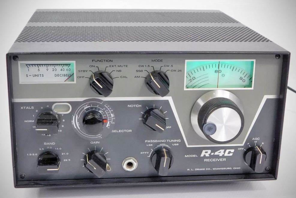
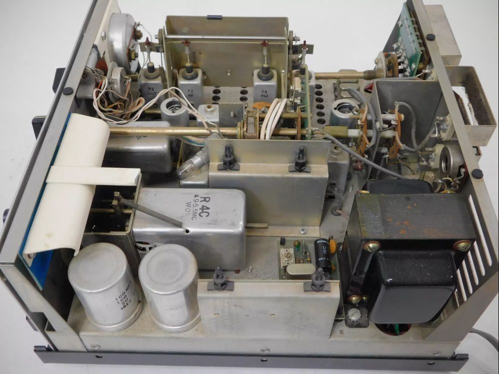
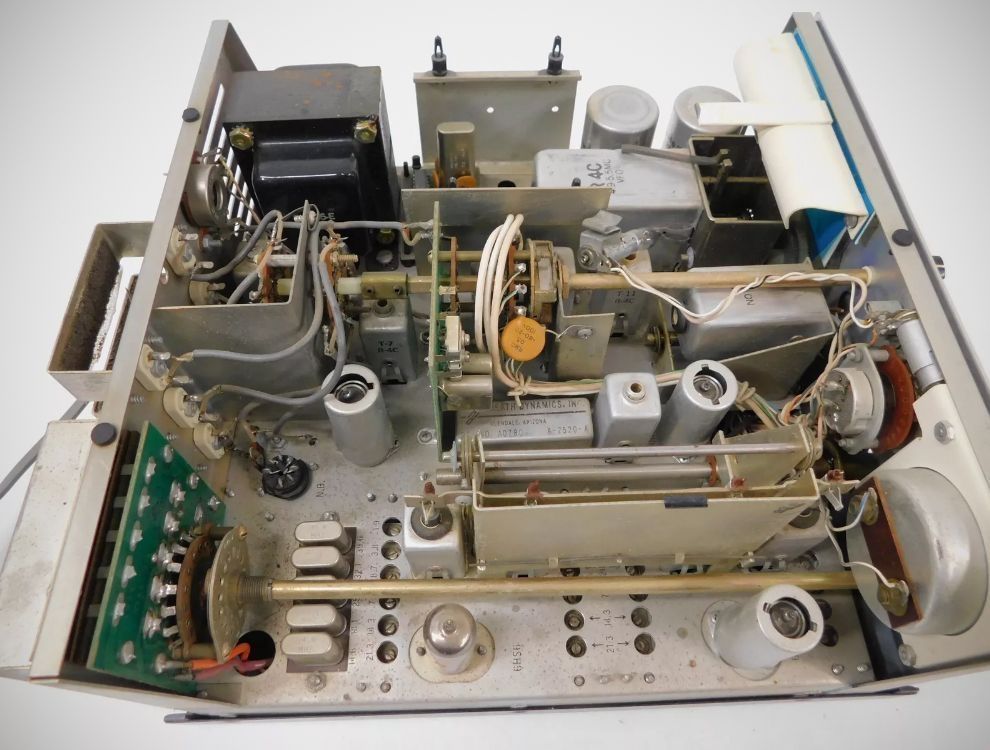
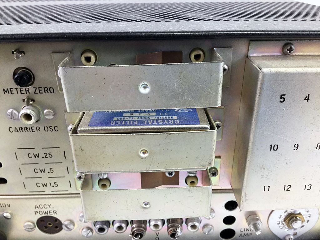
The R-4C mirrored the basic appearance of its 4-Line predecessors, but it was a very different receiver. The new triple-conversion model used an 8 kHz wide roofing filter in the first IF at 5645 kHz. The 5695 kHz second IF had a standard 2.4 kHz crystal filter and space for three optional crystal filters ranging in bandwidth from .25-6 kHz. Two L/C circuits in the 50 kHz third IF followed. The pass band tuning had been changed from mechanical to electrical. Additional flexibility was added to the AVC circuit.
The R-4C is also represents a further "solid-stateification" of the R-4 series, reducing the tube count to 6 (from 9 in the "B") by adding more solid state devices.
The number of extra crystal frequency ranges was increased to 15 (from 10 in previous versions).
Specifications
– Frequency Coverage: Covers 3.5 to 4.0 MHz, 7.0 to 7.5 MHz, 14.0 to 14.5 MHz, 21.0 to 21.5 MHz, and 28.5 to 29.0 MHz.
– Accessory Coverage: 15 accessory crystal sockets are provided. Coverage of any additional 500 kHz ranges between 1.5 and 30 MHz (except between 5.0 and 6.0 MHz) can be added by installing accessory crystals.
– Modes of Operation: SSB, CW, AM, RTTY.
– Sensitivity:
SSB Mode: 10 dB signal-plus-noise to noise ratio obtained on 80 M–10 M amateur bands with less than a 0.25 microvolt signal on the antenna terminal; on other frequencies less than 0.5 microvolt signal.
– Selectivity (As Supplied):
SSB Mode: 2.4 kHz at 6 dB, 4.2 kHz at 60 dB.
AM Mode: 8.0 kHz at 6 dB, 28 kHz at 60 dB.
– Selectivity (With Accessory Crystal Filters):
AM Mode (2 filters available): 6.0 kHz at 6 dB, 10 kHz at 60 dB; or 4.0 kHz at 6 dB, 7.5 kHz at 60 dB.
CW 1.5, CW .5, CW .25 Modes (3 filters available): 1.5 kHz at 6 dB, 3.0 kHz at 60 dB; 500 Hz at 6 dB, 1000 Hz at 60 dB; or 250 Hz at 6 dB, 600 Hz at 60 dB.
– Stability: After warm up, frequency will not drift more than $\pm100$ Hz, including voltage variation of $\pm10\%$.
– Calibration: Better than 1 kHz when calibrated at nearest 100 kHz calibration point.
– Spurious Responses: Internal spurious response less than the equivalent of a 1 microvolt antenna signal on all amateur bands.
– Image Rejection (11.29 MHz above desired): Over 70 dB below 23 MHz, 60 dB above 23 MHz.
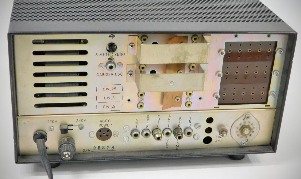
– Input Impedance: 52 Ohms nominal.
– Audio Output Impedance: 3.2 Ohms to speaker or headphones; 3000 Ohms anti-vox.
– Audio Output: 0.7 Watt at AVC threshold, 2 Watts maximum at less than 5% T.H.D.
– AGC: Audio output increases 3 dB maximum for an RF input increase of 100 dB above AGC threshold. AGC threshold is typically 1 microvolt.
Attack time: 1 millisecond.
Release times: Slow (1 second), Medium (350 mSec), Fast (50 mSec).
Tube and Semiconductor Complement
– 6BA6 RF Amplifier
– 6EJ7 First Mixer
– 6BE6 Second Mixer
– 6EJ7 Third Mixer
– 6BA6 Last IF Amplifier
– 6EJ7 Premixe
– 2N5950 First IF Amplifi
– EP487 Power Supply Filter
– 2N5950 Source Follower
– 2N5953 Crystal Oscillator
– 2N3394 BFO
– 2N3394 AM Detector Amplifier
– 2N3877 AGC
– 2N5950 PTO
– 2N3394 Audio Amplifier
– 2N3394 Audio Amplifier
– 40310 Audio Output
– 2N3392 Crystal Oscillator
– 2N3563 PTO Buffer
– 2N5950 100 kHz Calibration Oscillator
– 2N3394 Calibrator Shaper
– U1: SN7473 Calibrator Divider
Power Requirements: 120/240 VAC, 50/60 Hz, 60 Watts
References
Adding electronic bandpass tuning. Ham Radio, Oct 1973, 58.