Note
QST, Nov 1969, p. 159.
CQ, Dec 1969, p. 7. (some information)
QST, Jan 1970, p. 159.
QST, Feb 1971, inside front cover.
QST, Nov 1971, p. 160.
QST, Apr 1972, p. 160.
QST, Jun 1973, p. 125.
QST, Mar 1975, p. 127. (specs)
QST, Apr 1976, p. 70. (with list of options)
QST, Dec 1977, p. 116.
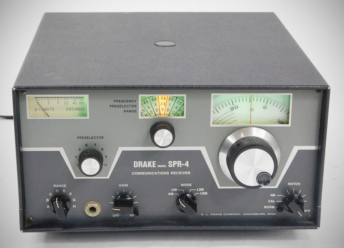
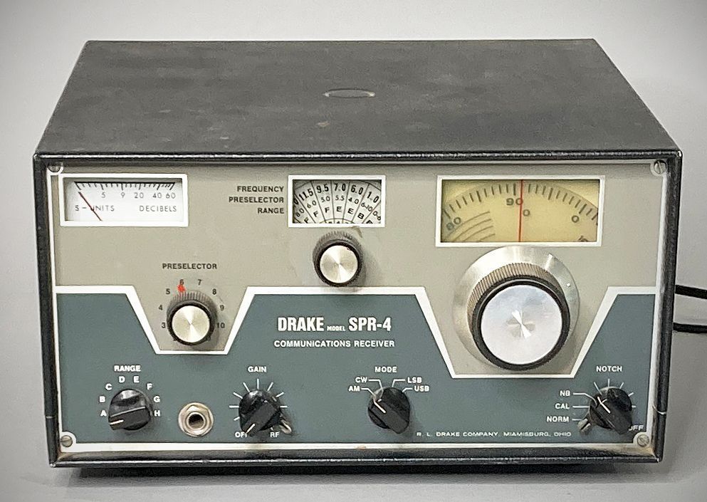
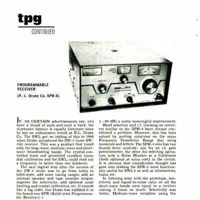
The Drake SPR-4 (Solid-state Programmable Receiver - 4) is a communications receiver introduced in 1969 by the R.L. Drake Company. Positioned primarily as a high-end general-coverage receiver for shortwave listeners, DXers, and commercial/maritime operators, it bridged the gap between Drake’s amateur-band-only line (such as the R-4 series) and full general-coverage requirements.
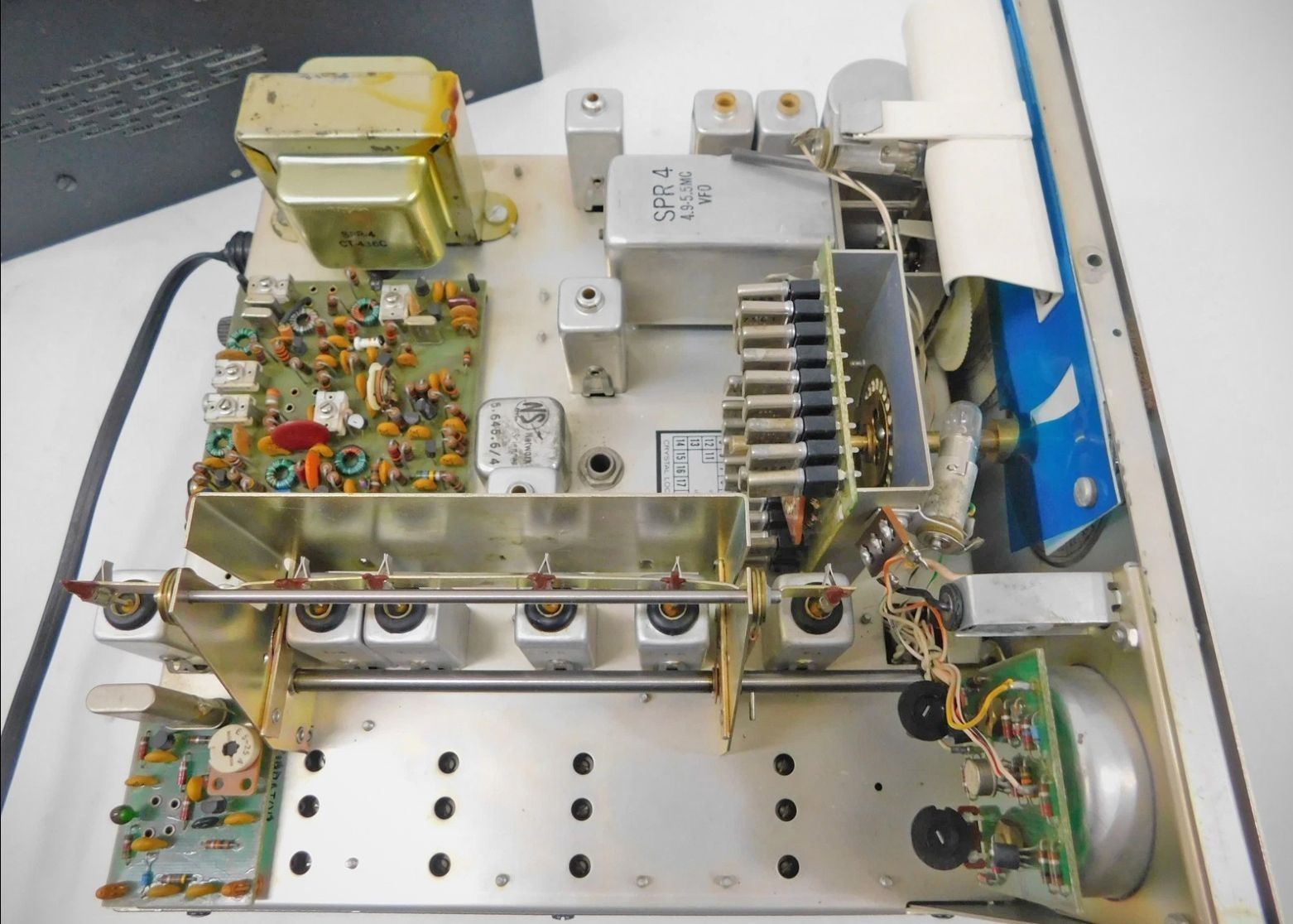
Unlike Drake's hybrid vacuum-tube R-4 series, the SPR-4 was an early all-solid-state design, utilizing 28 transistors, 1 IC, and 21 diodes.
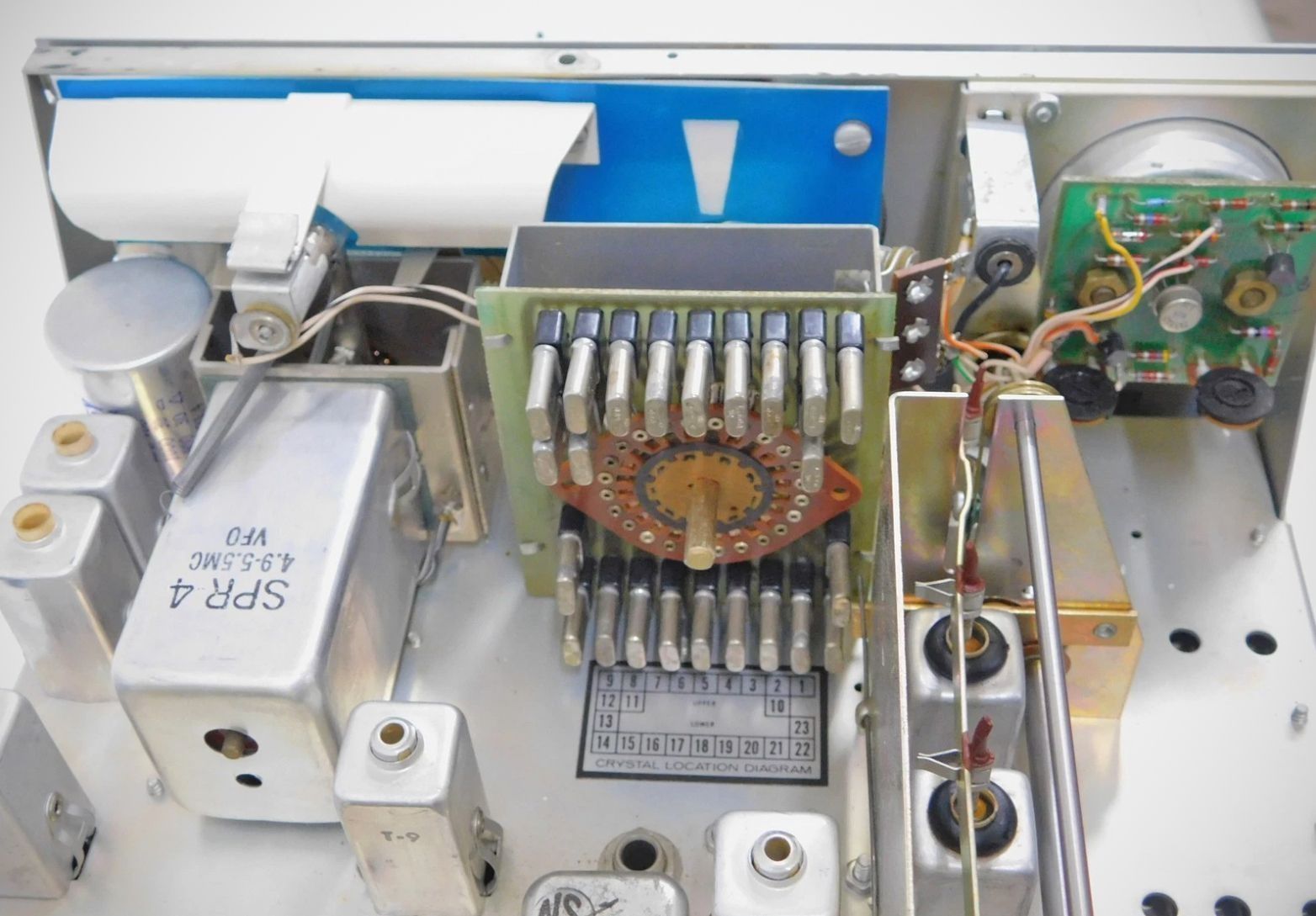
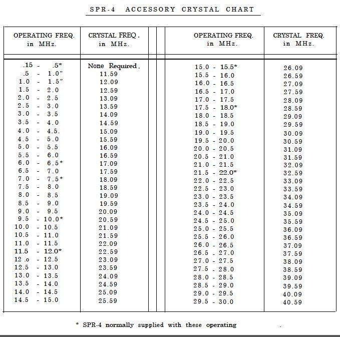
The receiver operates as a double-conversion superheterodyne receiver. High stability is achieved by using discrete heterodyne crystals for each 500 kHz frequency segment. The unit houses 23 crystal sockets on an internal bank, with 10 standard factory crystals covering key SWL and MW bands. Frequency tuning within each 500 kHz segment is controlled via Drake’s PTO, providing excellent mechanical linearity, low drift, and dial accuracy down to 1 kHz.
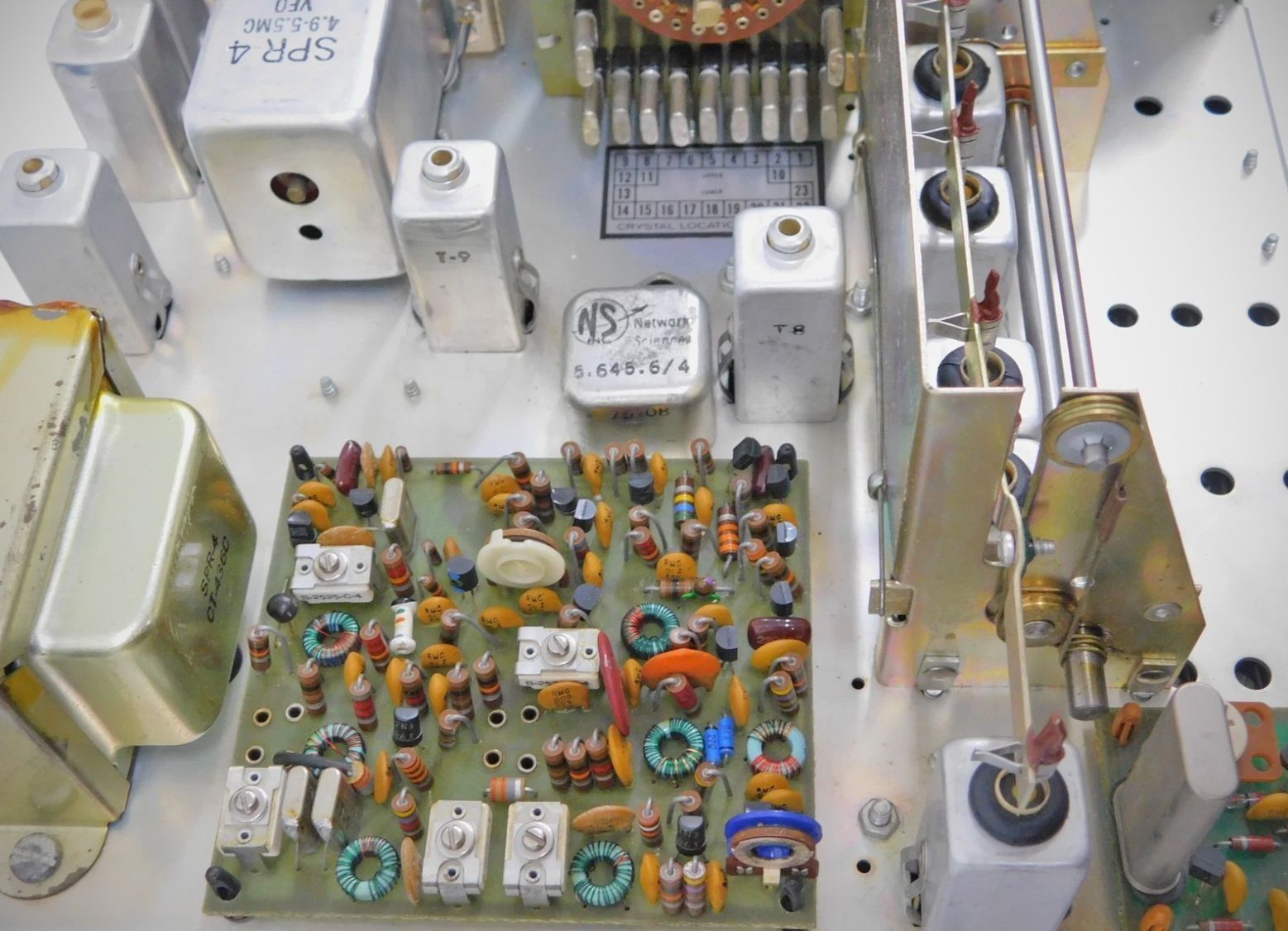
First IF is set at 5.645 MHz, and the second IF is at 50 kHz. The 50 kHz second IF allowed Drake to implement high-Q LC filtering with excellent selectivity, steep skirts, and an effective variable IF notch filter.
The receiver also features a manual front-panel preselector control that must be peaked for each frequency range, ensuring strong image rejection and dynamic range.
Factory Options & Accessories
– FS-4 Frequency Synthesizer: Eliminates the need to purchase individual crystals for each 500 kHz band.
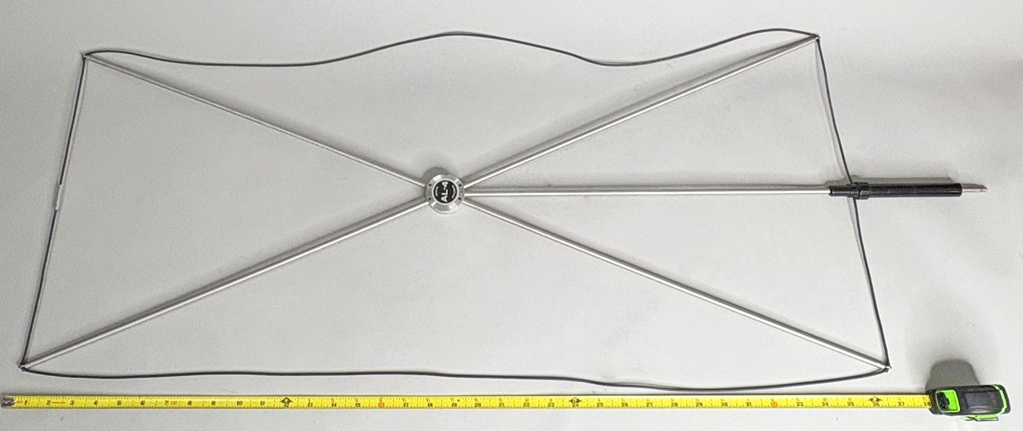
– AL-4 Loop Antenna: A top-mounted directional loop designed for longwave and mediumwave reception.
– 5-NB Noise Blanker: A solid-state module designed to clip pulse-type noise.
– SCC-4 Crystal Calibrator: Provides a 100 kHz reference marker to align the analog dial.
– RY-4 RTTY Adapter: Centers radioteletype audio tones within the 2nd IF filter passband.
– AT-4 Transceive Adapter: Allows the SPR-4 to be slaved with Drake T-4X transmitters for amateur radio transceive operation.
Specifications
– Frequency Coverage: Can be programmed with accessory crystals for 23 ranges (each tuning a 500 kHz band) from 0.5 to 30 MHz plus 150 to 500 kHz. Generous PTO dial overtravel allows an additional 50 kHz or more off each end of the range. Crystals supplied with the receiver allow coverage on the following ranges:
150 – 500 kHz
0.5 – 1.0 MHz
1.0 – 1.5 MHz
6.0 – 6.5 MHz
7.0 – 7.5 MHz
9.5 – 10.0 MHz
11.5 – 12.0 MHz
15.0 – 15.5 MHz
17.5 – 18.0 MHz
21.5 – 22.0 MHz
– Modes of Operation: AM, CW, SSB (Upper and Lower), and RTTY with RTTY adapter.
– Selectivity:
AM: 4.8 kHz @ 6 dB, 10.0 kHz @ 60 dB
SSB: 2.4 kHz @ 6 dB, 7.2 kHz @ 60 dB
CW: 0.4 kHz @ 6 dB, 2.7 kHz @ 60 dB
RTTY: With RTTY adapter, RTTY can be received in SSB (lower) or CW.
– Sensitivity:
SSB, CW, and RTTY: 0.25 microvolt for 10 dB S + N/N.
AM: 0.5 microvolt with 30% modulation for 10 dB S + N/N.
– Intermediate Frequencies: 1st IF: 5645 kHz; 2nd IF: 50 kHz.
– Frequency Stability: At room temperature, drift for all causes (including pm 10% change in supply voltage) is less than pm 100 Hz.
– Automatic Volume Control: AVC is used on all modes. Time constants are selected for optimum effectiveness on each mode. Audio output is held constant to 6 dB over a 100 dB range of input signals.
– Input Impedance: Approximately 50 ohms on ranges C – H. On ranges A and B, input is high impedance and plug-in loop antenna is low impedance.
– Audio Output Power: 3 watts into 4 ohm load (less into higher impedance loads).
– Hum and Noise: More than 60 dB below rated output.
– Calibration: Dial is accurate to better than ±1 kHz when calibrated to nearest 100 kHz calibration point.
Semiconductor Complement
Q1 2N3394 Loop Amplifier
Q2 2N3394 Range Crystal Oscillator
Q3 2N3563 PTO Buffer
Q4 SFC4982, MFE3007 RF Amplifier
Q5 SFC4982, MFE3007 Premixer
Q6 2N5950 PTO Oscillator
Q7 2N5245 1st Mixer
Q8 2N5245 1st Mixer
Q9 B5030 D.C. Regulator
Q10 SFC4982, MFE3007 2nd Mixer
Q11 2N5245 Crystal Oscillator
Q12 B5030 Audio Amplifier
Q13 B5030 Audio Amplifier
Q14 2N5949, MPF102 S-meter Amplifier
Q15 2N3394 Audio Amplifier
Q16 2N4125 Audio Amplifier
Q17 2N5950, MPF102 Crystal Oscillator Buffer
Q18 2N4125 AVC Amplifier
Q19 2N3394 Audio Amplifier
Q20 2N3394 Audio Amplifier
Q21 2N3566 Negative Supply Driver
Q22 2N3394 Audio Amplifier
Q23 SFC4982, MFE3007 IF Amplifier
Q24 SFC4982, MFE3007 IF Amplifier
Q25 2N3566 AVC Detector
Q26 2N4125 Mute Control
Q27 2N3394 BFO
Q28 2N3394 AM Detector
IC-1 CA3053 S-meter Amplifier
Power Requirements
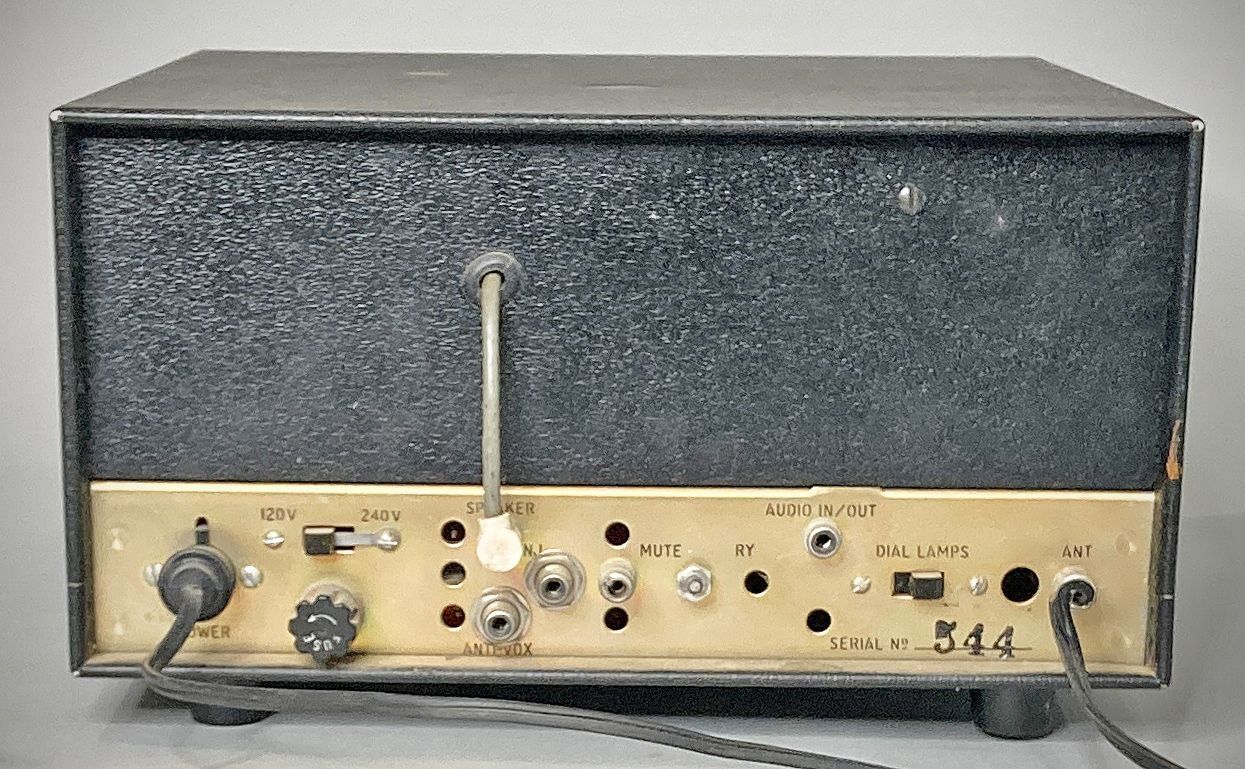
120 VAC or 240 VAC, 18 watts
12 VDC, 6 watts, 2.5 watts on 12 VDC with dial lamps turned off
Accessories
– FS-4 Frequency Synthesizer: Eliminates the need to purchase individual crystals for each 500 kHz band. ⚠️ Note that an accessory modification kit is required for use with the SPR4. Additionally, the 9.6 MHz reference crystal in the FS-4 must be replaced with a 9.59 MHz reference crystal.
– AL-4 Loop Antenna: A top-mounted directional loop designed for long wave and medium wave reception.
– 5-NB Noise Blanker: A solid-state module designed to clip pulse-type noise.
– SCC-4 Crystal Calibrator: Provides a 100 kHz reference marker to align the analog dial.
– RY-4 RTTY Adapter: Centers radioteletype audio tones within the 2nd IF filter passband.
– AT-4 Transceive Adapter: Allows the SPR-4 to be slaved with Drake T-4X transmitters for amateur radio transceive operation.
References
Review. Popular Electronics, Nov 1969, p. 74.
Brief description. Ham Radio, Jun 1970, p. 75.
Review. Popular Electronics, Nov 1974, p. 66.