Note
QST, Feb 1965, p. 106.
QST, May 1966, p. 133.
QST, Apr 1968, p. 139. (T-4B)
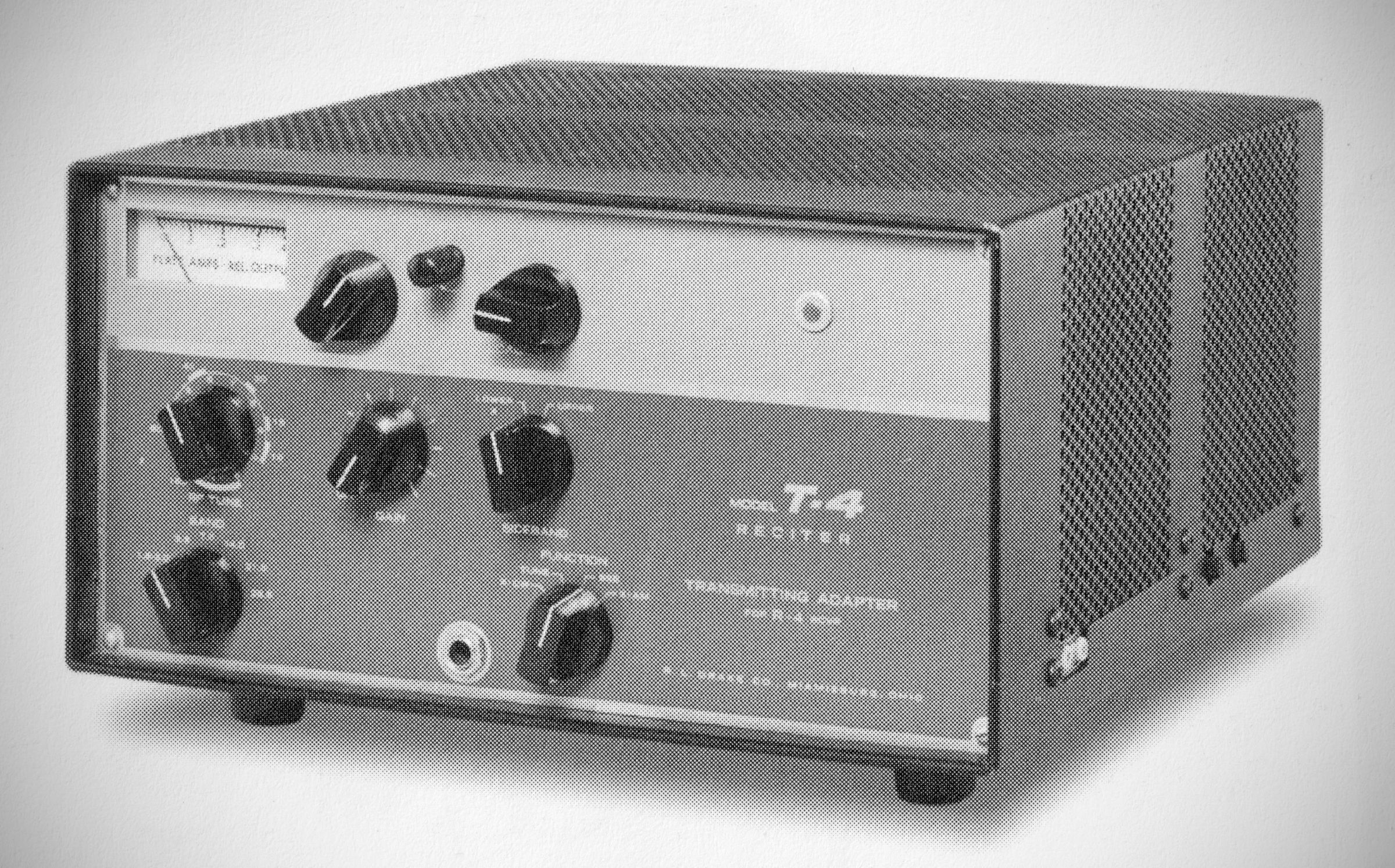
The T-4 Receiter is a receiver-controlled exciter, or, as Drake called it, a "transmitting adapter.". It was Drake's T-4X transmitter minus the PTO, designed to transceive with the R-4 receiver. It used a pair of 6JB6 tubes in the final and ran 200 watts PEP input on SSB. Input on CW was 180 watts, 50 watts on AM. Use of the T-4 with the R-4 series does not permit split frequency operation.
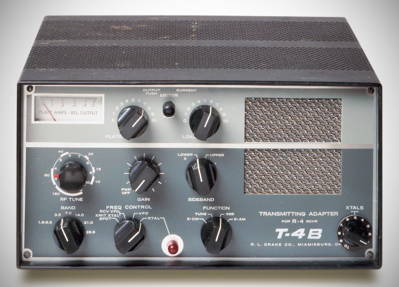
The T-4B is essentially the same device, but added a speaker for the R-4, and, more significantly, it added a frequency control switch and the ability to select from ten crystal controlled frequencies. This provided a limited means of operating split frequencies, and made the T-4B / R-4 combination suitable for novice use, for operation on MARS frequencies, and for net situations, for example. The unit is compatible with all versions of the R-4 series.
The Frequency control switch determined whether the T-4B or R-4 controlled the transmitting and receiving frequency. There were three possibilities, and a SPOT function:
– RCV VFO/XMIT XTAL: The T-4B is crystal controlled during transmit and the R-4/R-4A/R-4B determines the receiving frequency.
– VFO: The R-4/R-4A/R-4B determines both the receiving and transmitting frequencies for transceiving. In this mode, the T-4B XTAL switch has no effect.
– XTAL: The crystal selected by the XTAL switch on the T-4B determines both the receiving and transmitting frequencies for transceiving. In this mode, the R-4 VFO and crystals have no effect.
– SPOT: Low level transmitter stages are switched on and the receiver is not muted to allow the receiver to be tuned to the T-4B.
Specifications
– Frequency Coverage:
3.0– 30 MHz except 5.0– 6.0 MHz.
11.0– 11.5 MHz uses crystal control only.
In addition, either 1.8– 2.3 MHz or 2.0–3.0 MHz is included.
– Frequency Control: As previously described
– Stability: Less than 100 Hz after warm-up. Less than 100 Hz with a 10% change in line voltage.
– Modes of Operation:
SSB: Upper or lower sideband on all bands. VOX or Push-to-Talk.
CW: Grid-block keying. VOX circuit is keyed for automatic transmit-receive switching. Keyed sidetone oscillator for monitoring. Shifted carrier system with no spurious output.
AM: Built-in controlled carrier AM modulation. Compatible with SSB linear amplifiers. VOX or Push-to-Talk.
RTTY: Adaptable to RTTY operation.
– Sideband Suppression: 60 dB or better.
– Carrier Suppression: 60 dB or better.
– Average Distortion Products: In excess of 30 dB down.
– Frequency Response: Through the filter, 350 to 2750 Hz at 6 dB down.
– Input Power:
SSB and AM: 200 watts
CW: 200 watts
– Output Power:
SSB and AM: 120 watts or more
CW: 120 watts or more
– Output Impedance: Nominal 52 ohms, adjustable with pi-network (SWR should be 2:1 or less).
– Microphone Input: High impedance.
– AGC: Operates on SSB to prevent flat-topping due to overdrive.
– Carrier Balance Control inside
Tubes (11 total) & Semiconductor Complement
– 12BA6: IF Amplifier
– 12BY7: Driver
– (2) 6JB6: Power Amplifier
– 12AX7: Mic. Amp / Sidetone Osc
– 6EV7: VOX Amp
– 6HS6: Buffer
– 6AU6: AM Modulator
– 12AX7: AGC Amp
– 0A2: Voltage Regulator
– 6AU6: Mixer
– (3) 1N483A: VOX & Anti-Vox Rectifiers
– (4) 1N541: Balanced Modulator
– 1N483A: Trigger
– 1N270: Output Meter Detector
– 1N483A: Sidetone Keyer
– MPF-102: Xtal Oscillator
Power Requirements
Model AC-4 Power Supply: Operates on 120/240 VAC, 50/60 Hz.
Model DC-4 Power Supply: Operates on 12 VDC negative ground and has a 120 VAC 300–400 Hz output to operate R-4/R-4A/R-4B receivers.
Power Supply Specifications
– 650 VDC at 200 mA average and 330 mA maximum, with 10% regulation from 66 mA to 330 mA and maximum ripple under 1%.
– 250 VDC at 120 mA with 10% regulation from 82 mA to 120 mA (includes the effect of the 650 V supply change if both voltages are drawn from the same transformer). Maximum ripple under 1/4\%.
Bias: –45 to –65 VDC adjustable filtered bias into a 33k ohm load.
Filaments: 12.6 VAC or DC at 3 amps.