Note
QST, Feb 1965, p. 106. 1965–1967
QST, Jan 1968, p. 119. (T-4XB) 1967–1973
QST, Mar 1973, p. 119. (T-4XC ) 1973–1978
QST, Apr 1975, p. 97.
QST, Apr 1976, p. 103. (extra space for WARC bands)
QST, Dec 1977, p. 152.
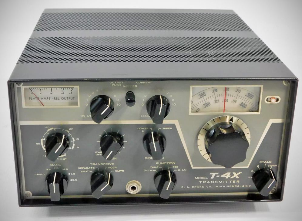
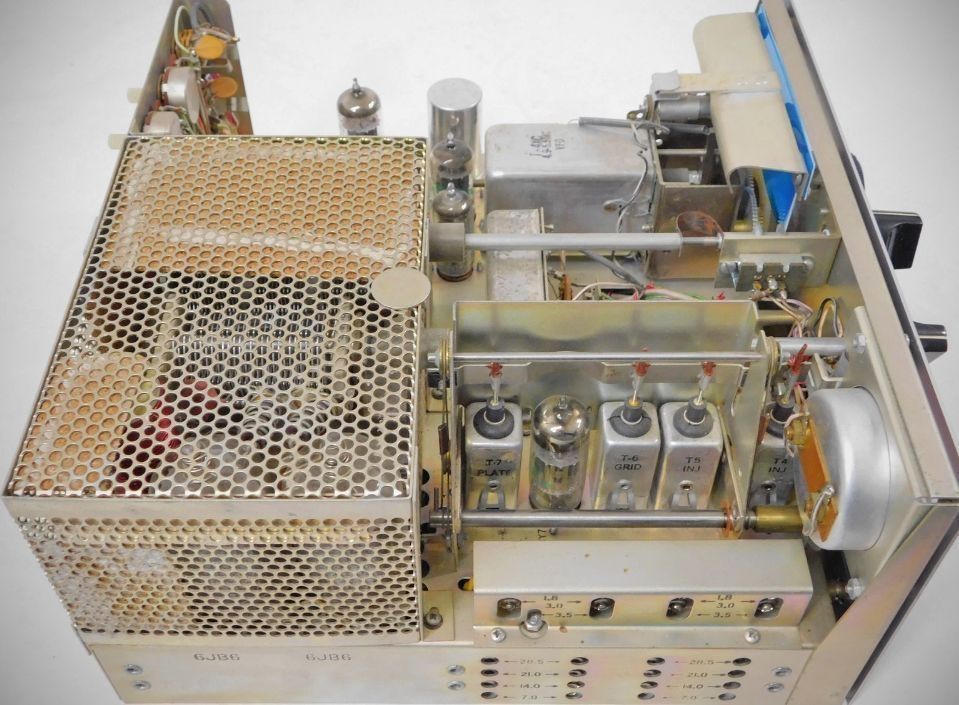
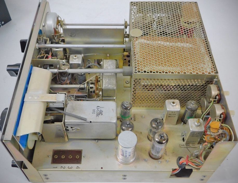
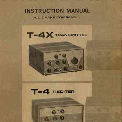
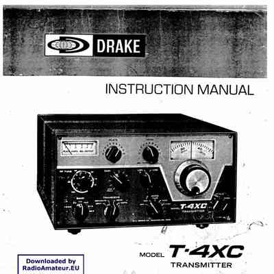
The T-4X series transmitters were designed to pair with the R-4 series receivers. A front-panel switch selected the transmitter or receiver PTO, or allowed them to be used separately.
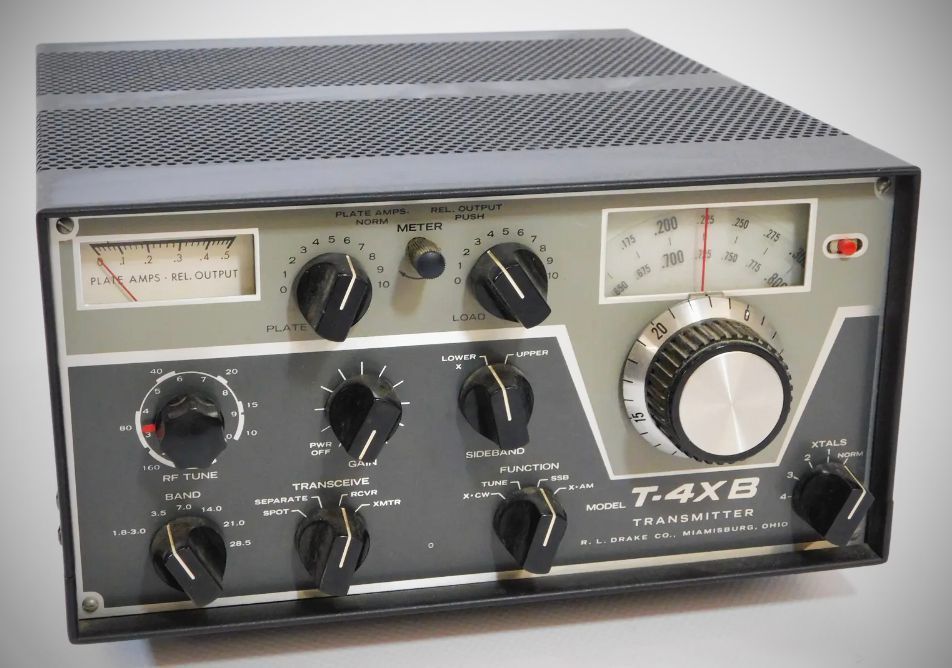
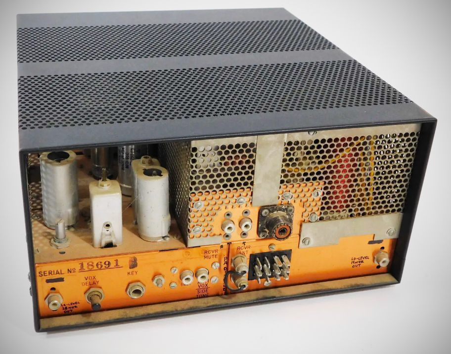
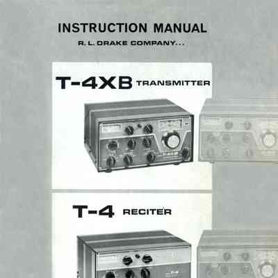
The T-4XB only included minor changes such as moving the mic jack to the right side of the cabinet.
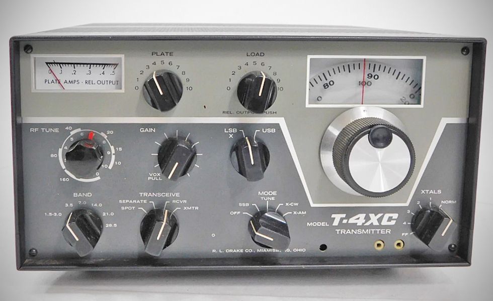
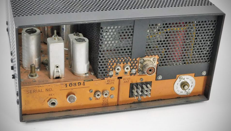
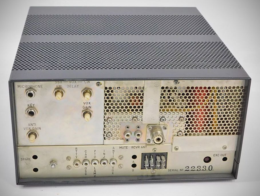
The T-4XC PTO had a new, more easily-read dial, and the mic input connector and VOX controls were moved from the side of the transmitter, where they had been located on the T-4XB, to the rear panel, and the addition of a front panel crystal socket.. Other changes included the deletion of the 0A2 voltage regulator tube and its repalcement with solid-state devices. The T-4XC also had provisions for AFSK RTTY operation.
Specifications (all versions)
– Standard Coverage: 3.5–4.0 MHz, 7.0–7.5 MHz, 14.0–14.5 MHz, 21.0–21.5 MHz, and 28.5–29.0 MHz with the supplied crystals.
– Accessory Coverage: Includes four accessory crystal sockets for coverage of additional 500 KHz ranges between 1.8 and 30.0 MHz.
– Excluded Frequencies: 2.3–3.0 MHz, 5.0–6.0 MHz, and 10.5–12.0 MHz.
– Main Dial: Calibrated 0 to 500 KHz and 500 to 1000 KHz in 5 KHz divisions.
– Vernier Dial: Calibrated 0 to 25 KHz in 1 KHz divisions.
– Calibration Accuracy: Better than 1 KHz when calibrated to the nearest 100 KHz point.
– Stability: Less than 100 Hz after warm-up; less than 100 Hz with a 10% change in line voltage.
Modes:
SSB: Upper or lower sideband on all bands via VOX or push-to-talk.
CW: Grid-block keying. The VOX circuit is keyed for automatic transmit-receive switching, and a built-in sidetone oscillator is keyed for monitoring. The shifted carrier system produces no spurious output.
AM: Built-in controlled carrier AM modulation (compatible with SSB linear amplifiers) via VOX or push-to-talk.
RTTY: VFO is easily adaptable to FSK. The signal frequency shifts in the same direction and amount on all bands for a given dial setting.
– Sideband Suppression: 40 DB above 750 Hz. (60 db, T-4XC)
– Carrier Suppression: 60 DB or better.
– Average Distortion Products: In excess of 30 DB down.
– Frequency Response: 300 to 2600 Hz at 6 DB down.
– Input Power:
SSB and AM: 200 watts
CW: 200 watts
– Output Power:
SSB and AM: 120 watts or more
CW: 120 watts or more
– Output Impedance: Nominal 52 ohms, adjustable via pi network (SWR should be 2:1 or less).
– Microphone Input: High impedance.
– AGC: Operates on SSB to prevent flat-topping due to overdrive.
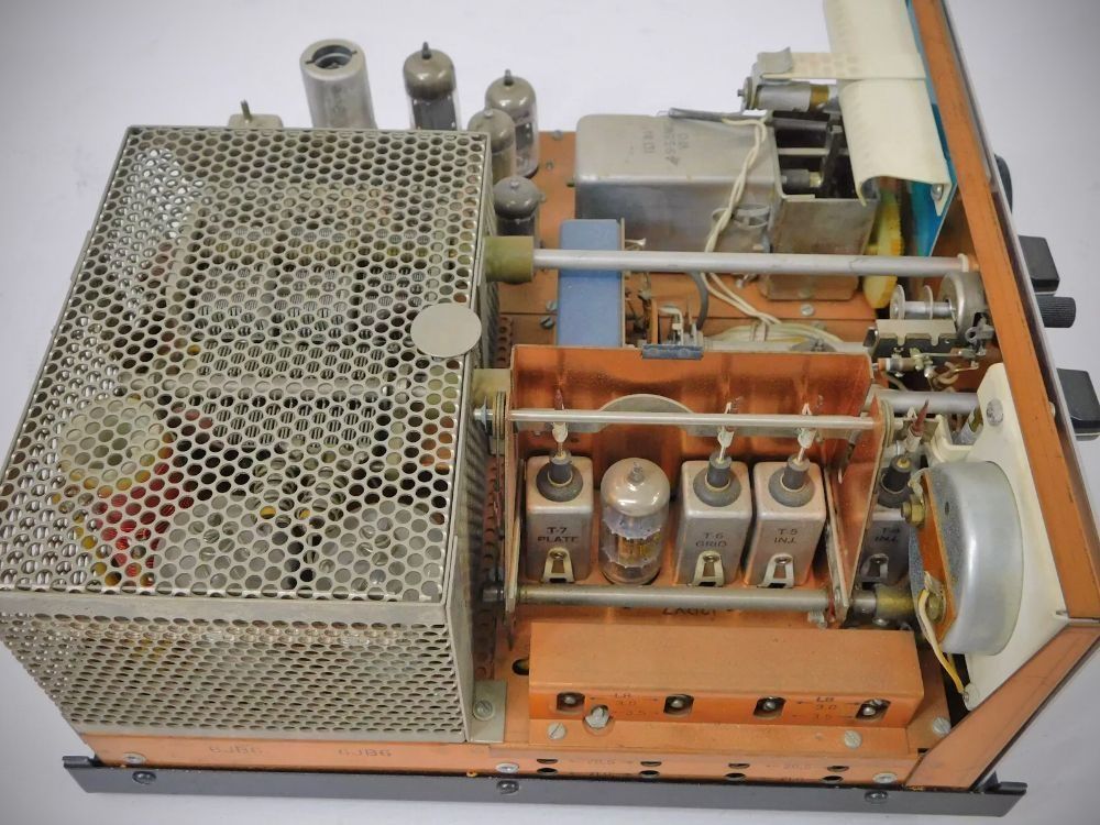
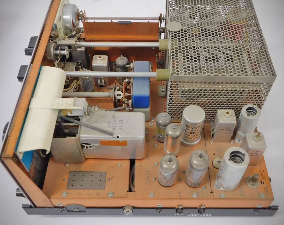
Tube Lineup (T-4X and T-4XB) (11 total)
– 12BA6 I.F. amplifier
– 12BY7 Driver
– 6JB6 (2 used) – Power Amp
– 12AX7 Mic amp / sidetone oscillator
– 6EV7 VOX amp
– 6HS6 Premixer
– 6AU6 AM modulator
– 12AX7 AGC amp / Carrier oscillator
– 0A2 Voltage regulator
– 6AU6 Mixer
Tube Lineup (T-4XC) (10 total)
– 12AX7 Audio Amplifier / VOX
– 12BA6 IF Amplifier
– 6AU6 Mixer
– 12BY7 Driver
– 6JB6 Power Amplifier / Final
– 6JB6 Power Amplifier / Final
– 6AU6 AM Modulator / Audio
– 6EJ7 Premixer
– 12AX7 Speech Amplifier / Sidetone Oscillator
– 6EV7 VOX / Relay Control
Power Requirements (AC-3 Power Supply)
– High Voltage DC: 650 volts at 200 ma average and 330 ma maximum, with 10% regulation from 66 ma to 330 ma and maximum ripple under 1%.
– Medium Voltage DC: 250 volts at 120 ma with 10% regulation from 82 ma to 120 ma (includes the effect of the 650-volt supply change when fed from the same transformer). Maximum ripple under 1/4%.
– Bias Voltage: -45 to -65 VDC adjustable, filtered bias into a 33K ohm load.
– Filament Voltage: 12.6 volts AC or DC at 3 amps.
References
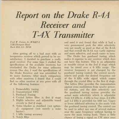
Review (T-4X). 73, Jan 1969, p. 76.
Adding syllibic VOX (T-4XB). Ham Radio, Aug 1976, p. 24.