Note
QST, May 1969, p. 159.
Allied Radio catalog 1970 (copyright 1969), p. 176.
QST, Feb 1971, p. 139.
QST, Nov 1971, p. 160. (TC-6 discontinued??)
QST, Apr 1972, p. 160. (only TC-2)
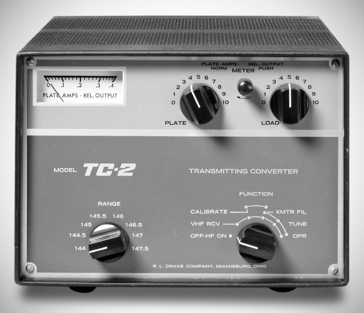
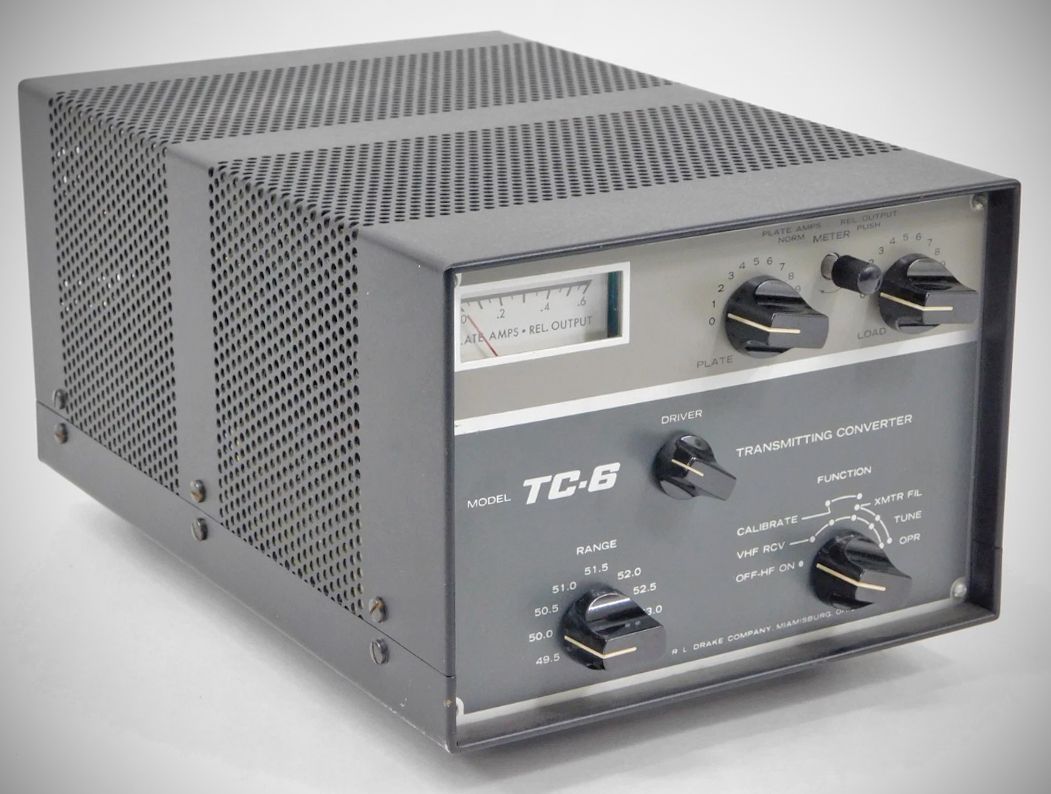
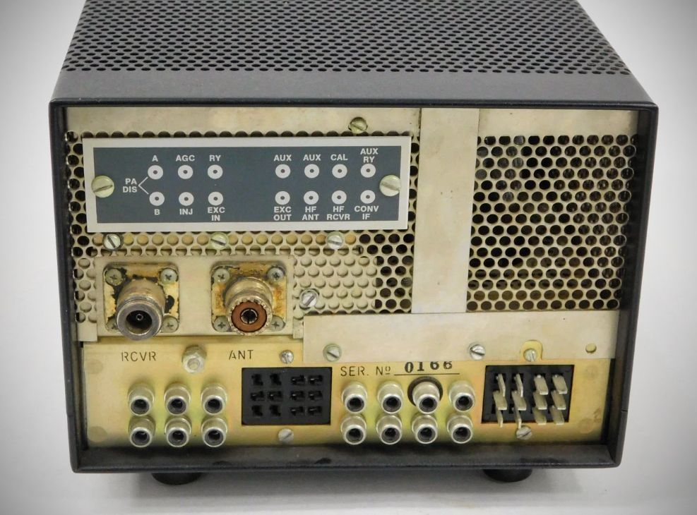
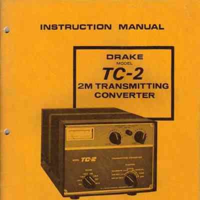
The Drake TC-2 and Drake TC-6 are vacuum-tube transmitting converters (transverters) introduced by the R.L. Drake Company in the late 1960s to extend the coverage of HF stations into the VHF bands. Designed to match the styling of the Drake 4-Line gear (such as the T-4X series and TR-4 transceivers), they translate a 14 MHz HF drive signal up to 2 meters and 6 meters.
– Frequency Coverage: 143.9 – 148 MHz
– Modes of Operation: SSB, CW, AM, and RTTY, determined by exciter
– Average Distortion Products: The odd order are typically 35 dB below PEP
– Input Power: 180 watts in CW and RTTY; 300 watts PEP on SSB and AM
– Output Impedance: Nominal 52 ohms (SWR less than 2:1)
– Injection Required: 0.25 V at 43.333 and 43.667 MHz
– Excitation Required: 0.25 V at 14.0 to 18.0 MHz
Specifications (TC-6)
– Frequency Coverage: 49.5 to 54.0 MHz.
– Mode of Operation: SSB, CW, AM, and RTTY; determined by exciter.
– Average Distortion Products: The odd order are at least 35 dB below PEP.
– Input Power: 300 watts of CW and RTTY. 300 watts PEP on SSB and AM.
– Output Impedance: Nominal 52 ohms with adjustable Pi-L network. (SWR less than 2:1).
– Injection Required: 0.25 V. at 36.0 and 36.5 MHz (from SC-6).
– Excitation Required: 0.25 V. at 13.5–17.5 MHz.
Tube Lineup (TC-2) (4 total)
V1 6EJ7 Mixer
V2 6EJ7 Pre-driver
V3 7558 Driver
V4 8643 Power amplifier
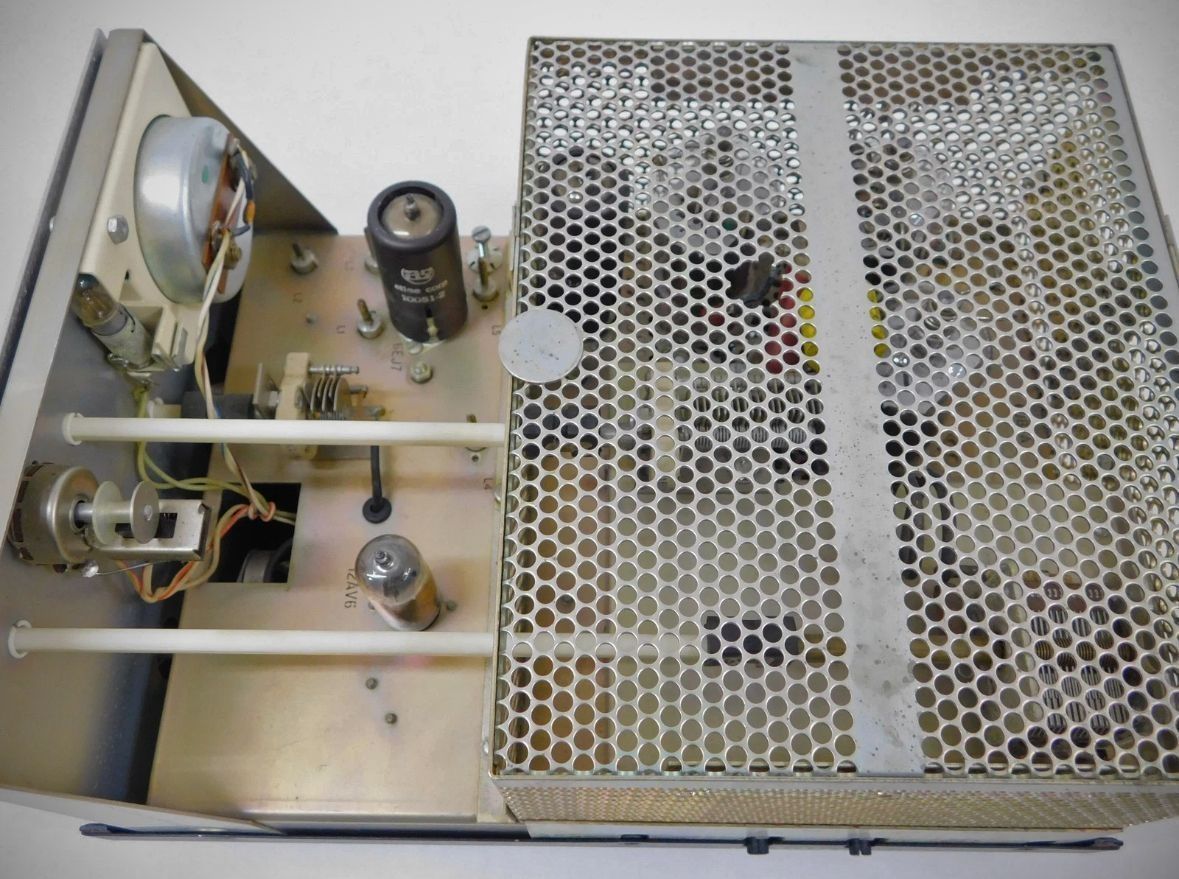
Tube LIneup (TC-6) (7 total)
V1 6EJ7 Mixer
V2 6GK6 Driver
V3 12AV7 AGC
V4 6Bj6 Power amplifier
V5 6Bj6 Power amplifier
V6 6Bj6 Power amplifier
Power Requirements:
12.6 VAC or DC @ 2.4 A.
250 VDC @ 100 mA, no more than 1/4% ripple.
650 VDC @ 540 mA max., 300 mA avg., less than 1% ripple.
75 VDC into a 33 K load.
All voltages are obtained automatically when using the TC-2(6) with a T-4X series, or TR-3/4, with a single Drake power supply.