Note
QST, Nov 1968, p. 175.
CQ, Dec 1968, p. 9. (full specs)
QST, Apr 1969, p. 167.
QST, Feb 1971, p. 157.
QST, Nov 1971, p. 160.
QST, Apr 1972, p. 160.
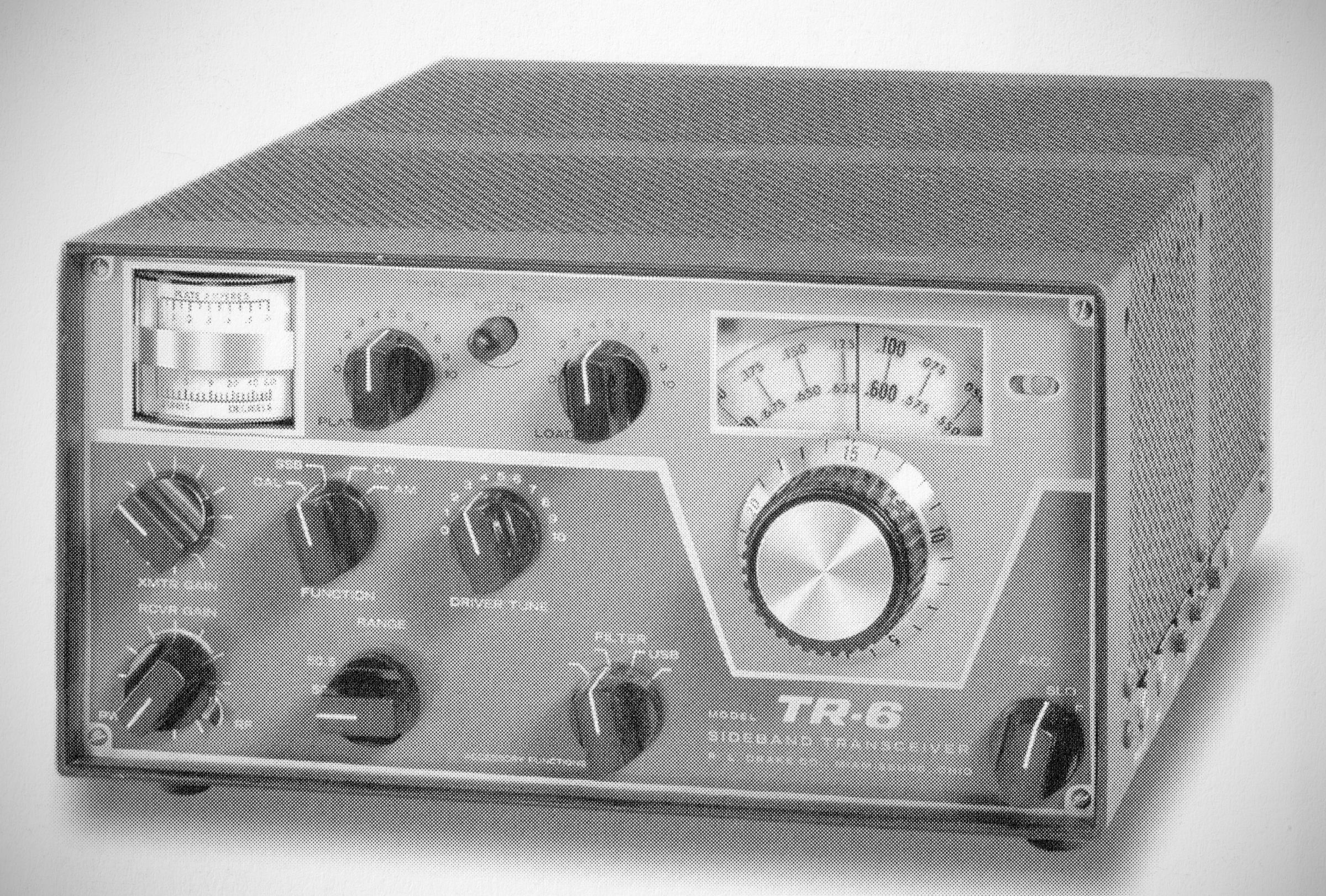
The TR-6 transceiver provided full coverage of 6 meters with 1 kHz dial calibration and 300 watts input on CW, SSB, and AM (PEP on the phone modes). The TR-6 used 19 tubes, 7 transistors, 3 FETs, and 12 diodes. Its final amplifier was three 6JB6 sweep tubes in parallel. One of Drake's AC or DC power supplies was required.
Features
– Frequency Coverage: Full coverage of the 6-meter band (49.4 to 54.0 MHz) plus MARS.
– IF Bandwidths: Four selectable IF bandwidths using a front panel switch—2.4 kHz upper sideband (USB, supplied), 2.4 kHz lower sideband (LSB), 6.0 kHz AM, and 0.3 kHz CW.
– Detector & Modulation Options: Function switch selects between a product detector or envelope detector, alongside a built-in AM screen modulator. Compatible with linear amplifiers.
– Carrier Adjustments: No carrier balance or carrier insertion adjustment required for AM or CW. Features a shift carrier CW system.
– VFO & Tuning: Ultra-stable linear VFO covering 600 kHz in one range with 1 kHz readability.
– Built-in Functions: Built-in PTT, VOX, ANTI-VOX, and 100 kHz calibrator.
– ALC & Metering: ALC prevents flat-topping. Features two meters providing readouts for ALC, S-Meter, Transmitter Plate Current, and Relative RF Output.
– Split-Frequency Operation: External VFO support (via Drake RV-6, as well as RV-3 or RV-4) allows split-frequency operation up to 600 kHz.
– AGC: Front-panel selectable Fast or Slow AGC for receiving (ideal for meteor scatter work).
– Front End Performance: Uses FETs in the receiver front end, achieving high sensitivity (less than 0.1 µV required for a 10 dB S+N/N ratio on SSB).
– Transverter & Accessory Support:
Inputs and outputs provided for the Drake TC-2 or other 2-meter transverters, with all switching handled internally via the band switch.
– Extra input and output jacks (13.9 to 14.5 MHz) for converters and outboard receivers, permitting simultaneous monitoring of multiple frequencies.
Here are the technical specifications for the Drake TR-6 6M Transceiver as outlined in Section II of the manual:
Specifications
– Frequency Coverage: 49.4 to 54.0 MHz in 9 overlapping 600 kHz ranges (49.9 to 51.0 MHz with crystals supplied).
– Frequency Adjustment: Solid state linear permeability tuned VFO permits continuous frequency coverage.
– Dial Calibration: 1 kHz divisions; dial accuracy is within pm 1 kHz if calibrated at nearest 100 kHz point.
– Calibrator: 100 kHz calibrator built in.
– Frequency Stability: Less than 100 Hz overall drift per hour after 15 minutes warm-up period; less than 100 Hz for 10% supply voltage change.
– Split Frequency Operation: Transmitting and receiving frequencies may be separated by up to 600 kHz by use of the RV-6 or FF-1 accessories or an external receiver.
– Modes of Operation: SSB, AM, and CW.
– Automatic T/R Switching: With multi-contact relay. Front panel switching provided for 2m-transverters.
– IF Bandwidths: 4 filters switchable from front panel (USB filter provided).
– Sensitivity: Less than 1/10 microvolt for 10 dB S+N/N ratio at 2.4 kHz bandwidth.
– Selectivity:
6 dB bandwidth 2.4 kHz nominal.
50 dB bandwidth 7 kHz maximum, with USB filter provided.
– Accessory filters switchable from front panel available for LSB, AM (6 kHz at 6 dB), and CW (0.3 kHz at 6 dB).
– Audio Response: 400 to 2800 Hz at 6 dB.
– Input: 50 ohms unbalanced.
– Output: 4 ohms unbalanced; speaker and headphone output provided.
– Output Power: 2 watts at 10% HD.
– AVC: Output variation less than 3 dB for 60 dB input change. Drake AVC system provides fast attack (less than 100 micro-seconds) for pop-free, pump-free, distortion-less automatic volume control. Release time switchable from front panel (1 second on "slow", 200 milliseconds on "fast").
– Detectors: Switchable from front panel. Product detector for SSB and CW; envelope detector for AM.
– Noise Blanker: On-off switch for accessory noise blanker provided on front panel.
– 14 MHz Input: 13.9 to 14.5 MHz receiving input/output jack provided for converters and/or outboard IF receivers. T/R muting contact for outboard receiver provided.
– S-Meter: Input level meter with 100 dB range provided.
– Power Input: 300 W minimum PEP on SSB; 300 W PEP (75 W peak carrier compatible with SSB amplifiers) on AM; 260 W CW.
– Output Impedance: 50 ohms nominal, unbalanced; 2:1 maximum SWR, loading adjustable from front panel.
– Modes: SSB (upper sideband provided, lower sideband with accessory filter); AM (controlled carrier screen modulator built in); CW (grid block keying shaped for click-free keying). Modes selectable with front panel switch.
– AGC: Amplified automatic gain control prevents flat-topping and provides moderate speech compression in the SSB mode.
– Carrier Insertion and Shift: Automatic carrier insertion on AM; shift carrier system on CW.
– Inputs: Closed circuit type key jack for CW; high impedance high level microphone input on SSB and AM (3 mV peak RMS minimum required for full PEP output). Manual gain control for CW and SSB/AM provided on front panel.
– VOX and PTT: VOX and ANTI-VOX built in. Separate VOX and ANTI-VOX gain controls provided. PTT contact provided on microphone jack. VOX also effective on AM and keyed CW, providing automatic semi break-in CW.
– Audio Response: 400 to 2800 Hz at 6 dB.
– Carrier and Sideband Suppression: 40 dB minimum sideband suppression above 1 kHz. 50 dB minimum carrier suppression.
– Distortion Products: Down 30 dB minimum from PEP level.
– Monitoring and Metering: Final plate current, AGC action, and relative output can be read on meters. Sidetone with separately adjustable volume provided for keyed CW.
– 14 MHz Output: 13.9 to 14.5 MHz transmitting output for 2m-transverter.
Tube Lineup
⚠️ Note specified manufactures.
V1: 0A2 Voltage regulator
V2: 12AV5 Sidetone ocs
V3: 6BZ6 2nd receiver mixer
V4: 6EJ7 2nd transmitter mixer
V5: 6BZ6 callibrator (RCA)
V6: 6GK6 Driver (Sylvania)
V7: 6AU6 1st mixer
V8: 6BJ6 Power amp (Sylvania, matched)
V9: 6BJ6 Power amp (Sylvania, matched)
V10: 6BJ6 Power amp (Sylvania, matched)
V11: 6BZ6 1st IF amp
V12: 12BA6 2nd IF amp
V13: 12AX7 AGC (Sylvania)
V14: 13DE7 AM modulator
V15: 12BA6 Transmitter IF amp
V16: 6GX6 product detector
V17: 6GK6 AF output
V18: 12AX7A Mic amp (RCA)
V19: 6EV7 VOX amp
Power Requirements
– 650 volts DC at .5 A maximum with good regulation.
– 250 volts DC at .175 A with low ripple.
– 60 volts adjustable into 30 K load.
– 12.6 volts at 5.5 A continuous.
Drake models AC-3 and AC-4 power supplies provide all necessary voltages for operation from AC input, and models DC-3, DC-4, and DC-24 provide power from DC input.
References
Review. QST, Jul 1970, p. 54.