Note
QST, May 1978, pp.120–122.
QST, Sep 1979, pp. 202–205. (full specs)
QST, Jan 1980 p. 109.
QST, Apr 1981, p. 103.
QST, Jan 1982, p, 101.
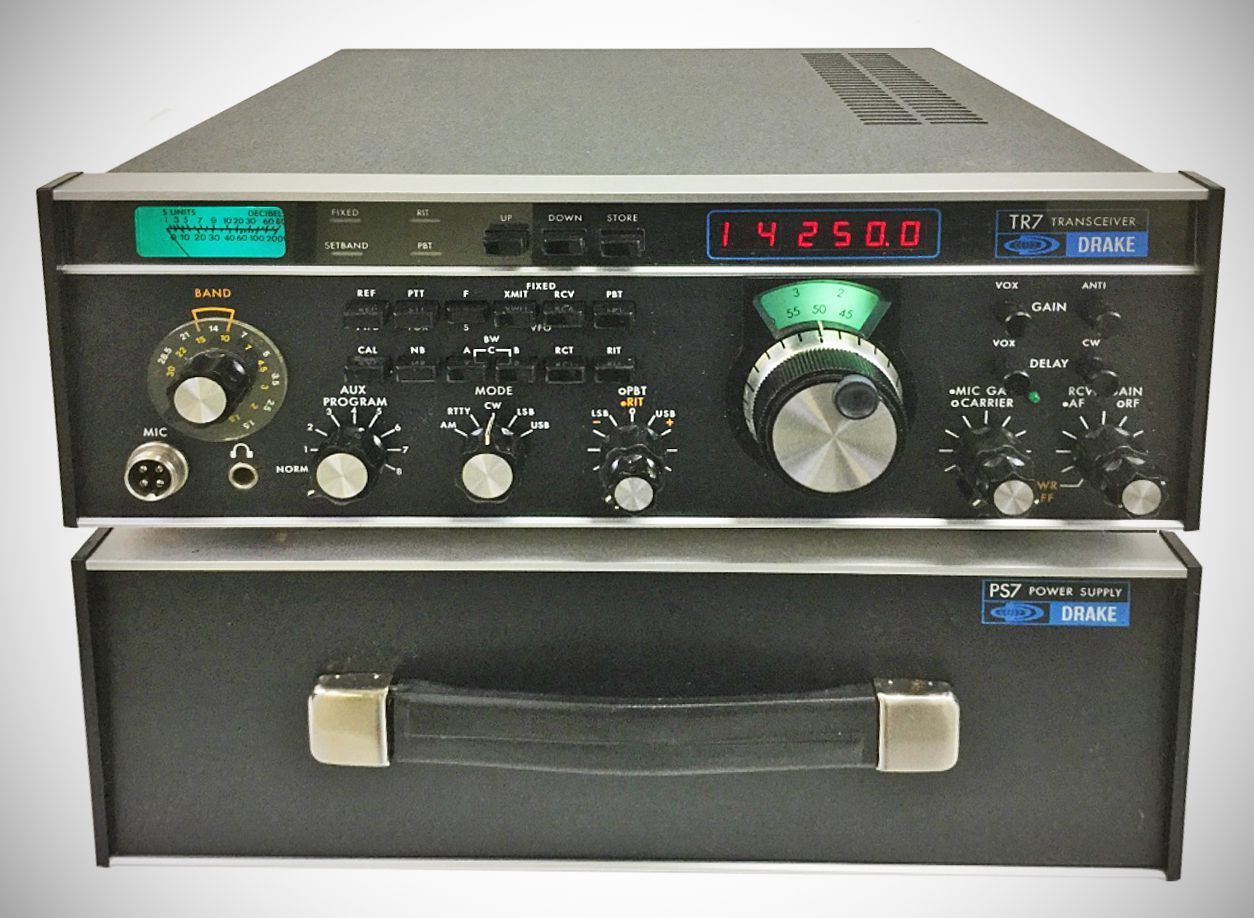
The R.L. Drake Company introduced the TR-7 transceiver and 7 -Line equipment in the spring of 1978. The TR-7 used a combination of synthesizer and PTO frequency control. All circuits were solid-state and broad-banded. It covered the 160-10 meter amateur bands and, with the addition of accessories such as the DR-7 and Aux-7, provided continuous receiver coverage from 0 to 30 MHz. The basic TR-7 had an analog dial and the DR-7 General Coverage/Digital Readout board was necessary for the digital dial and continuous 1.5-30 MHz tuning. The TR-7 used up-conversion and a 48 MHz first IF. The transmitter was rated at 250 watts input on CW and SSB. It also transmitted AM using the upper sideband and 80 watts carrier power; basic TR-7.
The TR-7 was Drake's most ambitious project to date, but could not compete with the rigs of Icom and Yaesu.
Lots of optional add-ons.
The TR-7 transceiver from the is the first commercially available amateur trans-
ceiver that uses a 48 MHz IF. This concept allows great flexibility in frequency coverage as well as providing greatly improved image rejection.
Reception through the entire range of 1.5 through 30 MHz is provided by the TR-7, and, with the use of the Aux-7 Range-Program board, the range can be expanded t o cover from 0 to 30 MHz. The up-conversion technique, along with the synthesized PT0 frequency control, makes this extended frequency coverage
possible.
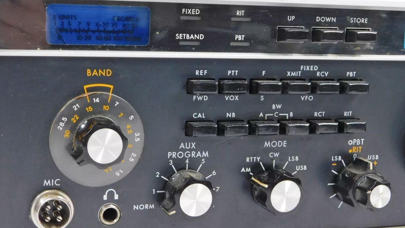
Full passband tuning is another feature of the receiver portion of the unit. It is possible to tune from the top edge of one sideband, through zero, to the bottom edge of the other sideband. The range is also wide enough to allow tuning through RTTY signals. This ability to place a wanted signal at the proper spot in
the filter passband is a great aid when working on the crowded amateur bands.
Further improved reception can be obtained by installing optional receiving selectivity filters in the rig; you can select the desired filter by push button switches on the front panel. Also, a unique system permits you to select the receiving filter independently of the transmitter mode or function. Thus you can transmit on CW but receive with an SSB filter, or even transmit on one sideband
while receiving the other.
Optional filter widths include 300 Hz, 500 Hz, 1.8 kHz, or 6 kHz.
On the transmit side of the unit, optional programmable coverage for non-amateur-band parts of the spectrum are available. Proof of license for operation out of the amateur bands must be submitted to the R.L. Drake Company before obtaining these options, however. This feature also takes care of any possible later expansion of the amateur frequencies.
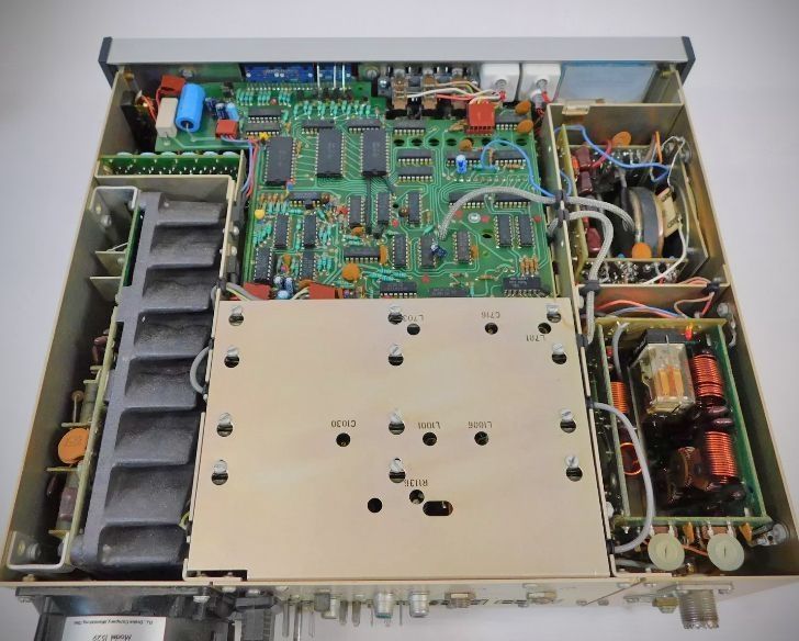
The all-solid-state design and broadband tuned circuits means that there are no preselector or peaking circuits to contend with in the TR-7. The power amplifier is designed for continuous-duty SSB and CW operation. The efficient, internal heat- sink provides enough dissipation in free air for full power on all modes except SSTV or RTTY; these high-duty-cycle transmissions are provided for by an optional fan for extra cooling.
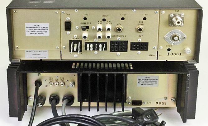
The transmitter is rated at 250 watts input on all modes, and the PS-7 AC power supply is designed to provide continuous-duty power for any mode. This supply also accepts input voltages of 90-132 VAC and 180-264-VAC, at 50 to 60 Hz, which makes it ideal for overseas locations.
The TR-7 may also be operated from any nominal 13.6 VDC supply capable of providing 3 Amps on receive and 25 Amps on transmit.
Additional features of the include a digital frequency readout, which will provide accuracy of ±100 Hz, or an analog readout with ±1 kHz accuracy when properly calibrated. The digital frequency display can be used as a test instrument with frequency capability of up to 150 MHz, with access to the counter input through a rear panel connector.
Power-output metering is obtained by making the standard S-meter double as a built-in watt meter/SWR indicator.
BASIC SPECIFICATIONS
Receiver sensitivity: less than 0.5 uV for 10 dB S + N / N ratio.
Image and IF rejection: greater than 80 dB
Power input: 250 watts PEP SSB, 250 watts CW.
Spurious output: greater than 50 dB down.
Harmonic output: greater than 45 dB down.
lntermodulation distortion: 30 dB below PEP.
Undesired sideband suppression: greater than 60 dB at 1 kHz.
A wide range of optional features are available, including a noise blanker, mobile mounting kit, crystal filters, a speaker in a matching cabinet, and a similarly matching remote VFO.
References
Adding WARC and LF bands. QST, Jul 1982, p. 20.