Note
HW-2036 1976-1978 $269.95
HW-2036A 1978-1980 $269.95 HW
Smarting badly from the failure of the HW-2026, Heath took great pains to ensure that its replacement would perform without a hitch. After a long, difficult summer and endless testing, Heath unveiled the new rig in its 1976 Christmas catalog—complete with charts displaying its spectral purity.
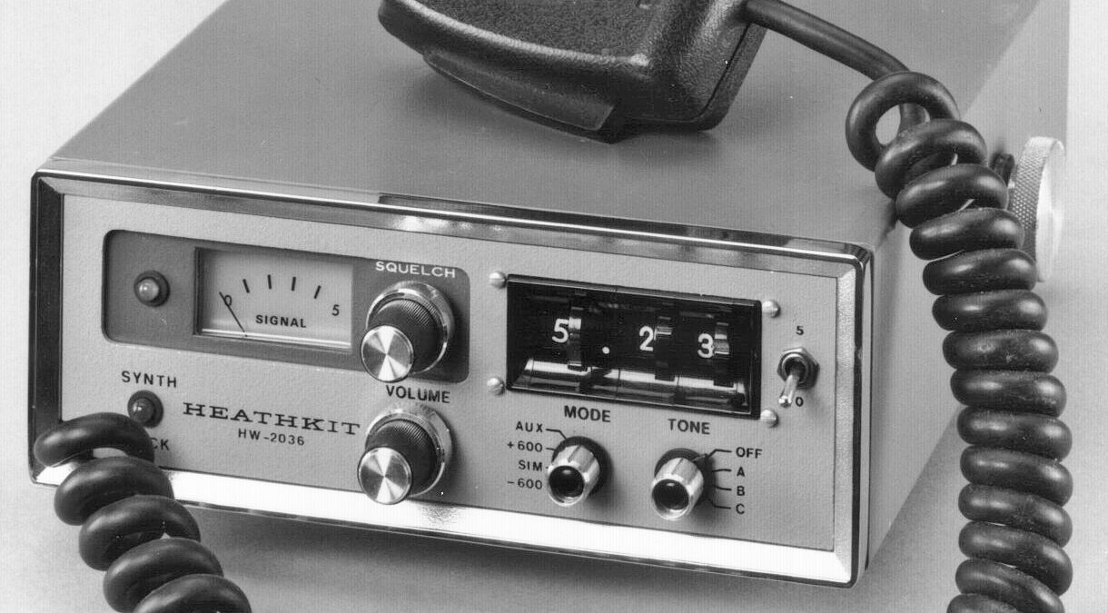
Cosmetically the new rig was almost identical to the 2026, but Heath gave it a new number so no one would mistake it. It was designated as the HW-2036. There were some substantial differences. The HW-2036 uses a 10 MHz time base; the 2026 uses a 1 MHz time base. The 2026 has both a tone burst and a continuous tone encoder. The 2036 has only a continuous tone encoder, but gave a choice of three switch selectable frequencies between 70 and 200 Hz.
Perhaps most significant is that the 2036 offers both plus and minus 600 kHz transmitter offset, as well as simplex operation plus an auxiliary offset.
The HW-2036’s basic specifications are about the same as the 2026. The receiver features dual-conversion, an 8-pole crystal IF filter, IC limiting, Quad detection, and a double tuned front end with a MOSFET RF amp. The receiver has a sensitivity rating of better than 0.5 µV and a bandwidth of 6 dB down at 15 kHz. All birdies are less than 1.0 µV equivalent.
The transmitter puts out about 10 watts with harmonic and spurious emissions down 70 dB within 20 MHz of the carrier. Deviation is adjustable from 0 to 7.5 kHz. Front panel controls include on/off/volume, squelch, frequency selectors, mode, tone, 0 or 5 kHz, and a meter reading S-units and relative power.
As with the HW-2026, there are two LEDs that light up on the front panel. One indicates “channel busy” and the other indicates synthesizer lock. In normal operation this light should come on briefly whenever you key the mic, unless you dial in a frequency that is out of the band, or outside of the 2 MHz band segment chosen during construction.
The HW-2036(A) was supplied with a Turner 360C ceramic microphone, or optionally the Micoder microphone. The microphone is hard-wired—but watch for mods adding a mic connector.
Rear panel connections include an RCA jack for a 50Ω antenna (many have been user replaced with SO-239s) and an RCA jack for an external speaker. A rear panel switch selects between the internal speaker and an external speaker. There is no rear panel power connector—power input wires come out an opening in the rear panel.
The HW-2036 covers any 2 MHz segment of the band between 143.5 and 148.5. Note: Both transmitter and receiver must be aligned with the same 2 MHz portion of the band.
The only difference in the A version is in frequency coverage. The HW-2036A offers a full 4 MHz coverage—the entire two-meter band.
The HW-2036(A) is offered with the optional Micoder microphone, which features a built-in touch tone pad. The transceiver can be powered directly from a 12 VDC source and is polarity protected. AC operation requires an external 12 VDC power supply.
The two-tone green cabinet with chrome trim matches the HW-202 and the HW-2026. In 1980 the HW-2036A was replaced with the VF-7401, but there was a small gap in production.
References:
Review. CQ. Mar 1978, p. 51.
Review: Popular Electronics, May 1978, p. 79.
Improved antenna connection, input for RTTY audio. QST. Oct 1977, p. 46.
Frequency display for. Ham Radio. Jul 1978, p. 50.
Illumination for lever switches. Ham Radio. Jul 1978, p. 99.
Antenna socket short circuit potential. Ham Radio. Jan 1979, p. 80.
Updates / improvements. Ham Radio. Mar 1979, p. 63.
LED readout for. QST. Jun 1979, p. 17.
Channel switch visibility. QST. Aug 1979, p. 51.
Channel switch visibility. QST. Aug 1979, p. 51.
Carrier operated relay for. Ham Radio. Feb 1980, p. 58.
Temperature effects on bypass capacitors. QST. Jul 1980, p. 40.
Digital readout and scanning. Ham Radio. Nov 1980, p. 50.
Digital readout and scanning (more). Ham Radio. Jun 1981, p. 8.
Add scanning. 73 Amateur Radio. Dec 1980, p. 88.
Add PL level control. 73 Amateur Radio. Apr 1981, p. 96.
RECEIVER
Sensitivity: 15 db of quieting @ 0.5 µV or less
Squelch threshold: 0.3 µV or less
Audio output: 1.5 watts @ less than 10% THD
Image rejection: –45 db or better
Spurious rejection: –50 db or better
IF rejection: –80 db or better
Internal generated spurious signals: below 1.0 µV equivalent except at 146 and 148 MHz
Receiver bandwidth: 6 db @ 15 kHz minimum, 60 db @ 30 kHz maximum
De-emphasis: not specified
TRANSMITTER
Power output: 10 watts minimum @ 13.8 VDC into 50Ω load
Spurious and harmonic output:
spurious: –70 db within 20 MHz of carrier
harmonic: –60 db
Oscillator: approximately 6 MHz
Multiplier: x 24
Modulation: FM, adjustable from 0 to 7.5 kHz
Duty cycle: 100% with infinite SWR
Tone encoder: 3 tones, 70 to 200 Hz, approximately 700 Hz deviation
Transmitted offset: 0, –600 kHz, + 600 kHz, and provision for one other
GENERAL
Speaker impedance: 4Ω
Operating frequency range:
HW-2036: any 2 MHz segment between 143.5 to 148.5 MHz (transmitter lockout can be defeated for out-of-band operation)
HW-2036A:
Frequency increments: 5 kHz
Frequency stability: ±0.0015%
Operating temperature range: –15F to +125F
Power requirements: 12.6 to 16 VDC (13.8 nominal) at 2.6 amps (while transmitting), 700 mA (receiving, squelched)
Solid State:
diodes: (5) 1N458, (2) 1N191, (4) 1N4149, (1) 1N716A, (1) 1N2071, (1) 1N4002, (1) MV2107
transistors: (1) MPS6520, (2) 2N2369, (1) EL131, (1) 2N5294, (1) 2N3866, (1) 40673, (3) MRF502, (1) 2N5770, (19) MPSA20, (1) 2N6081, (1) 2N6080, (3) MFE131, (1) MPSA55
integrated circuits: (1) NE5558A, (1) NE555V, (1) UA703, (1) UA7805, (1) 78L05, (1) MC1357P, (1) TBA820, (2) SN7400N, (1) SN7473N, (3) SN7490N, (1) SN7492N, (1) MC4044P, (1) MC1648, (3) MC4016P
Photos, general information and specifications from "Heathkit: A Guide to the Amateur Radio Products," by Chuck Penson, WA7ZZE. Used with permission.