Note
The HW-99 is essentially an HW-9 with more power. The HW-99 is a fully solid state rig using a single conversion receiver with a broadband front end, a 4-pole crystal filter, and no RF amp. The rig is built on three circuit boards. It has an AGC circuit and an active audio filter with a bandwidth of about 450 Hz at 6 dB down, receiver sensitivity of better than 1.0 µV, and covers the lower 250 kHz segment of 80, 40, 15, and 10 meters. There are no provisions for WARC operation.
The transmitter was advertised as about 50 watts into a 50Ω load but often is found to be as high as 60 watts on 80 through 15 meters. The PA transistors are protected against high SWR. The transmitter ALC will deliver at least 90 percent of rated output with an SWR of less than 2:1.
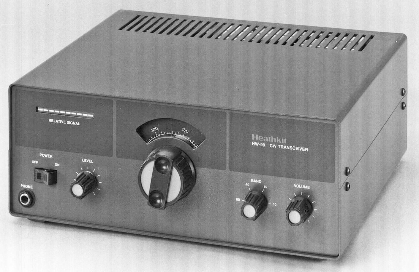
Features include a built-in AC power supply, a front panel LED bar graph display for S-units and relative power, an illuminated tuning dial, continuously variable RF output, and full QSK break-in operation up to 30 WPM.
There is no built-in speaker. Front panel controls include a power on/off rocker switch, RF level, band, volume, and main tuning. There is also a headphone jack on the front panel.
Rear panel connections include an SO-239 for a 50-75Ω antenna, a ground post, RCA jacks for a speaker (4 to 8Ω), and a key.
The HW-99 only lasted about a year and a half. It was viewed as expensive, featureless, and drifty. Heath’s own specs did little to persuade one that this was a stable radio—“typically less than 1 kHz per hour after 30 minutes warmup. Typically less than 150 Hz per 30 minutes after 90 minutes warmup.” An article in QST described a mod to fix the drift problem. See references below.
Note: There are no DC power input connections that would let the HW-99 be used in a battery-portable situation. A matching speaker (SP-99) was optional. The two-tone brown matches HW-9 and the “little brown box” series.
References
Review. 73 Amateur Radio. Apr 1987, p. 30.
Review. QST. Mar 1986, p. 43.
Curing thermal drift. QST. Jul 1989, p. 41.
AGC threshold control. QST. Mar 1990, p. 43
Frequency coverage:
3.5 to 3.75
7.0 to 7.25
21.0 to 21.25
28.0 to 28.25
Readout accuracy: 5 kHz divisions
Frequency stability: see text
Mode: CW only
Sensitivity: less than 1.0 µV for 10 db (S+N)/N
Selectivity: about 450 Hz @ 6 db
Passband center frequency: about 700 Hz
Audio output: 1 watt into 8Ω
Dynamic range: 70 db at maximum sensitivity
Image rejection: 50 db minimum
IF: 8830 kHz
IF rejection: 50 db minimum
Audio hum and noise: at least 40 db below maximum output
RF output power: 40 watts minimum on all bands; 50 watts nominal
Transmitter frequency offset: about 700 Hz lower on all bands
RF load impedance: 50Ω nominal, unbalanced
VSWR: at least 90% of rated power with less than 2:1
T/R operation: full QSK to 30 WPM
CW sidetone: about 700 Hz (level internally adjustable)
Operating temperature range: 15F to 105F
Power requirements: 120 VAC, 60 Hz
Solid State:
diodes: (3) 1N295A, (11) 1N458, (6) 1N191, (30) 1N4191, (2) 1N2071, (2) 1N4002, (2) S5A05
transistors: (1) MPS6520, (3) MPF105, (3) MPS6521, (1) 2N3866, (3) 2N5770, (5) MPSA20, (1) MJE171, (2) MFE131, (1) MPSA05, (4) MPSA55, (1) 2N4472, (1) MRF476, (1) MRF466
integrated circuits: (1) MC1349P, (1) MC1496G, (1) LM324N, (1) UA7812, (1) LM2904N, (1) LM388N-3
Photos, general information and specifications from "Heathkit: A Guide to the Amateur Radio Products," by Chuck Penson, WA7ZZE. Used with permission.