Note
QST, Aug 1961, p. 109.
Eico short form catalog 1965, p. 42.
Kit or wired
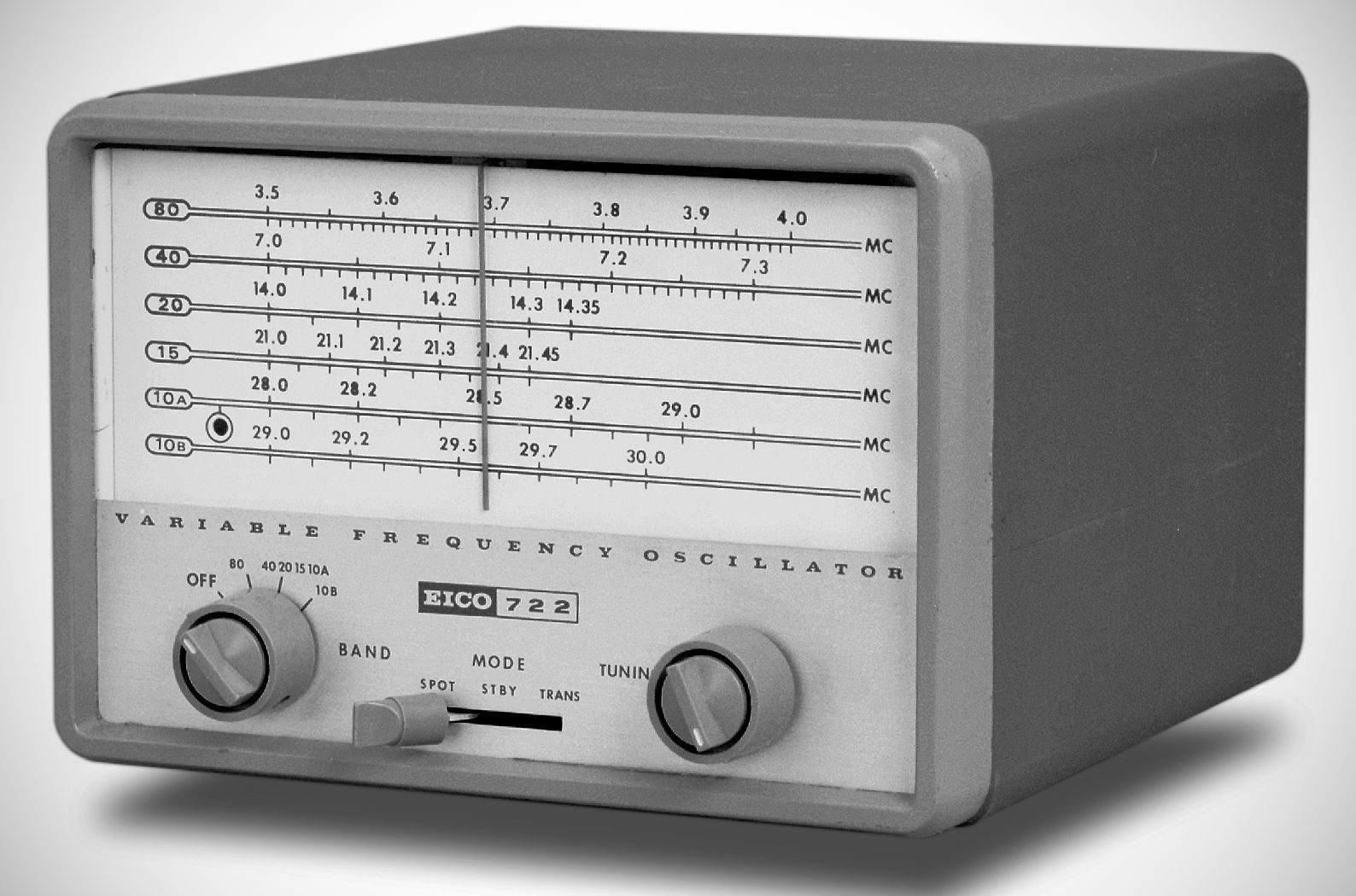
The Eico 722 VFO was introduced in 1961. Designed primarily for use with Eico's 720 and 723 transmitters, the 722 covers the 80-, 40-, 20-, 15-, and 10-meter amateur bands, it enables continuous frequency tuning across each band.
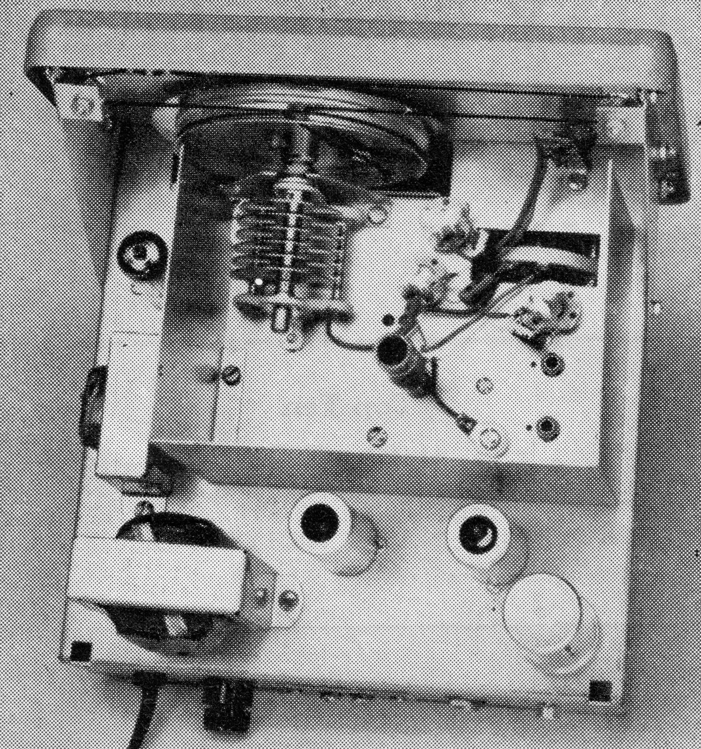
The 722 employs a 6AU6 oscillator, a 6CB6 buffer/amplifier stage, and an 0A2 voltage regulator to ensure signal stability and minimize drift. The unit’s design includes a well-shielded chassis, precision variable capacitor, and high-quality components to reduce frequency drift during warm-up—a common challenge in early VFO designs. The front panel features band-switching controls, a main tuning dial with fine calibration, and a mode switch. The output level is adjustable. The power supply uses silicon diodes.
The oscillator is an electron coupled, series-tuned, Colpitts type, using a 1 3/8" air core coil and temperature compensated capacitors. A high L to C ratio minimizes circulating tank current. The buffer/multiplier stage as "straight through" buffer amplifier on 80 meters, and as a doubler on all higher bands.
Frequency coverage: 80–10 (but not 11) meters
Output frequencies: 3.50–4.00 MHz, 7.00–7.30 MHz, 7.25–7.64 MHz
Calibrated bands: 3.50–4.00 MHz. 7.00–7.30, 14.00–14.40, 21.00–21.45, 28.00–29.20, 29.00–29.70
RF Output: 10–20 volts
Power: 117 VAC, 60 Hz
Tubes: (1) 6AU6, (1) 6CB6, (1) 0A2
References
Brief description. Electronics World, Dec 1961, p. 110.
Brief description. Popular Electronics, Dec 1961, p. 28.
Review: QST, Feb 1963, p. 48.
Review. Electronics World, Mar 1963, p. 70.
Review: CQ, May 1964, p. 31.