Note
Even after concluding that the SS-8000/9000 was too complex to sell in kit form, the company decided to try again with a kit-form transceiver. The HW-5400 would be the company’s final attempt.
The HW-5400 was originally conceived as a kit version of the Kenwood TS-120S. The idea of “kittizing” someone else’s products had been done before with modest success. Heath had done it the early 60s with the Thomas electronic organ, and with a Bally pinball machine, for example, and would do it again in the future with the Ameritron AL-80A, as the SB-1000 linear amplifier.
Turning a ready made product into a kit had the advantage of significantly reducing both engineering time and costs. And at a time when Heath’s amateur radio group was being systematically dismantled by Zenith, the concept was pretty attractive.
Unfortunately, negotiations with Kenwood went nowhere, and the idea was shelved. Heath then decided to go it alone, using the TS-120S as a road map, while adding changes and additional features that would make it uniquely Heath. The project was plagued by foreign competition and excessive engineering and design costs, and was troubled by persistent assembly and alignment problems.
Not that it wasn’t a good enough rig, it’s just that the production costs were so high Heath ended up having to sell it for about what you would pay for a ready-made transceiver with more features and fewer headaches. Add to this the 100 hours needed to put it together, and most of the advantages Heath originally had to offer were gone. Most hams opted out.
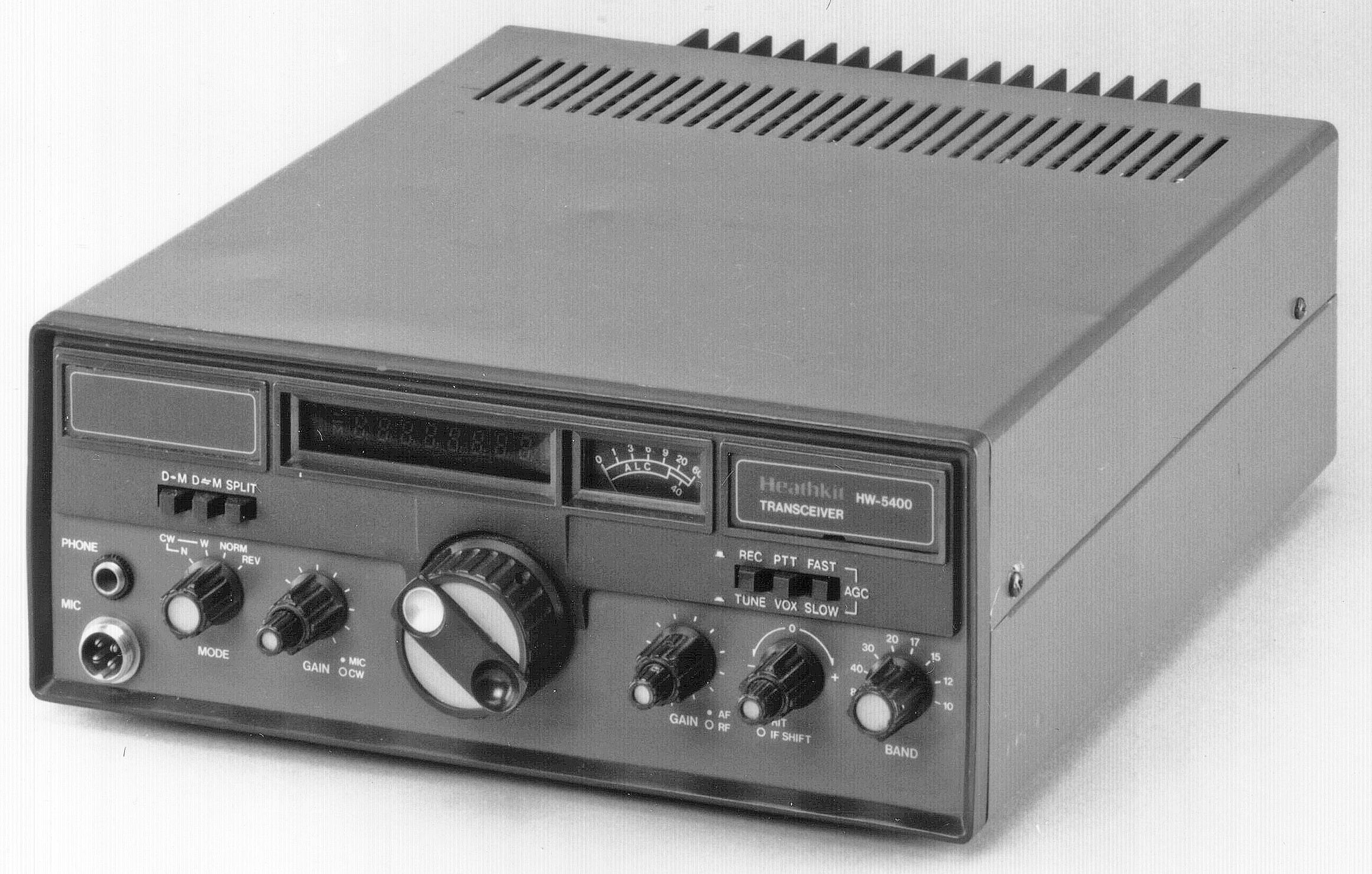
The fully solid-state HW-5400 covers 80-10 meters including the WARC bands. The transceiver is built around 15 circuit boards large and small, and a few other assemblies. The assembly and operations manuals, combined with the illustrations booklets, made a stack of paper nearly and inch and a half thick.
As with the SS-8000, Heath had exceeded the capability of the average person to assemble a kit, but this time the company chose to live with it. Mostly. So demanding was the assembly that toward the end of production, large portions of the 5400 were being shipped pre-assembled.
Of course, it didn’t help that Heath was changing the design on an almost daily basis. Changes were so frequent that Heath eventually abandoned its traditional soft bound assembly manual in favor of one in a three-ring binder. Still, once you (or the factory) got it working, it worked quite well.
Features include broadband design, two-speed tuning, automatic sideband selection (with manual override) and full QSK operation The green vacuum fluorescent display indicates frequency, T/R status, split operation, and mode.
The HW-5400 uses an optical encoder tuning scheme. In addition, the main tuning knob is fitted with a metal insert in one of its two finger indents. Touching this indent causes the receiver to tune in 1 kHz steps instead of the normal 50 Hz steps—very clever. Heath patented the idea.
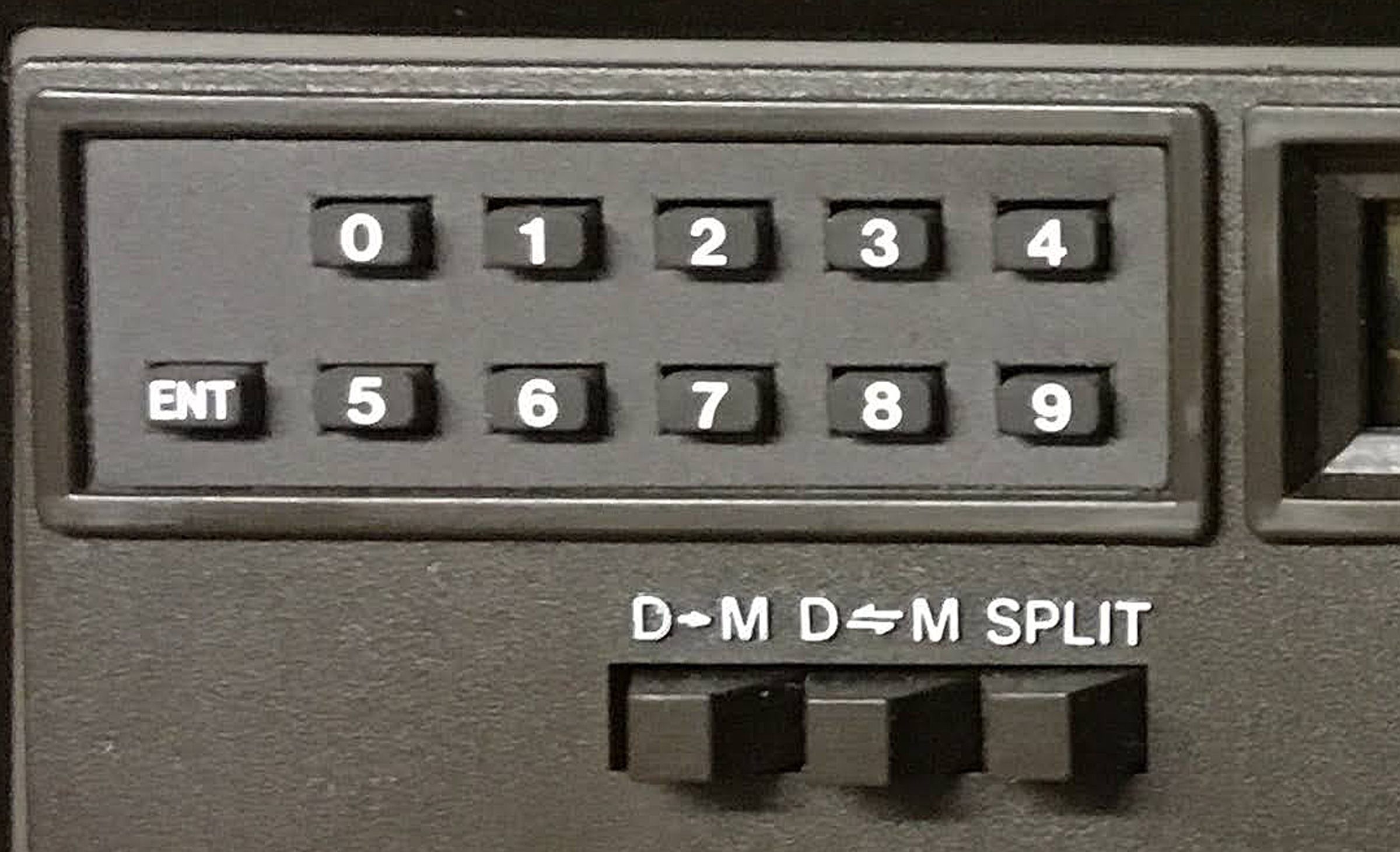
The frequency entry keypad seen in every advertising photograph is optional (HWA-5400-3).
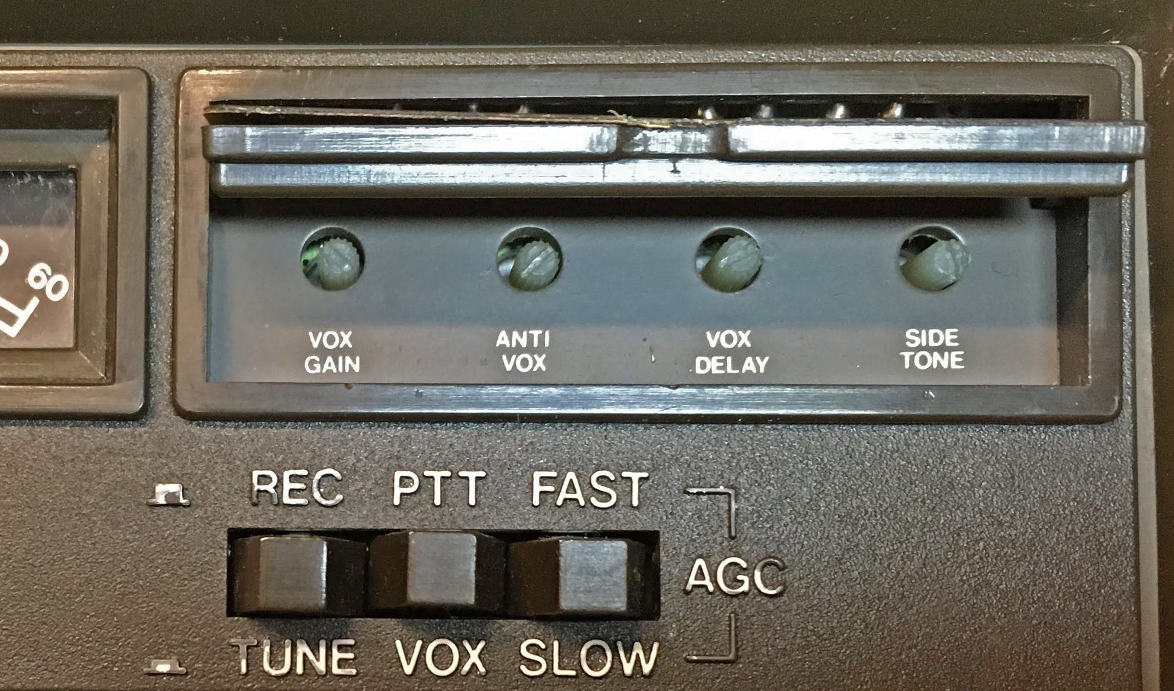
Front panel controls include main tuning, mode, mic gain, CW gain, AF gain, RF gain, RIT, IF shift, and band, as well as push buttons for receive/tune, PTT/VOX, AGC fast/slow, and memory management. VOX controls and sidetone level adjustment are located behind the Heath nameplate. The meter reads S-units and ALC/relative power.
A note regarding the IF shift control: The HW-5400 is a single IF superheterodyne design with a fixed IF determined by the crystal filter. The IF shift control does not shift the IF frequency, but instead shifts the BFO frequency in receive mode. So you are really just shifting the pitch of the demodulated IF signal without changing the bandwidth. A more accurate term might be “passband tune," as you tune the BFO through the receiver's IF passband.
Rear panel connections include an SO-239 for a 50Ω antenna, and RCA jacks for ALC and relay output for use with a linear amplifier. In addition there is an accessory socket for connection to the optional HWA-5400-1 power supply/speaker. This connector provides audio to a speaker. Why Heath did not provide a separate 3.5 mm jack for a speaker is a mystery. The connector also has “an essential sensor line for proper operation and remote on/off switching at the radio.” It is a voltage feedback line used to compensate for losses in the DC cable from the power supply. Lastly, the connector provides power input for memory back-up. It should be noted that supplying power for the memory backup is not necessary if you don’t plan to make use of the memory functions.
There is also a rear panel 4-pin Molex connector for DC power input, and a switch to disable the linear relay for more quiet operation when not using an amplifier. The 4-pin Molex connector is both unusual and inconvenient. Finding one may be difficult.
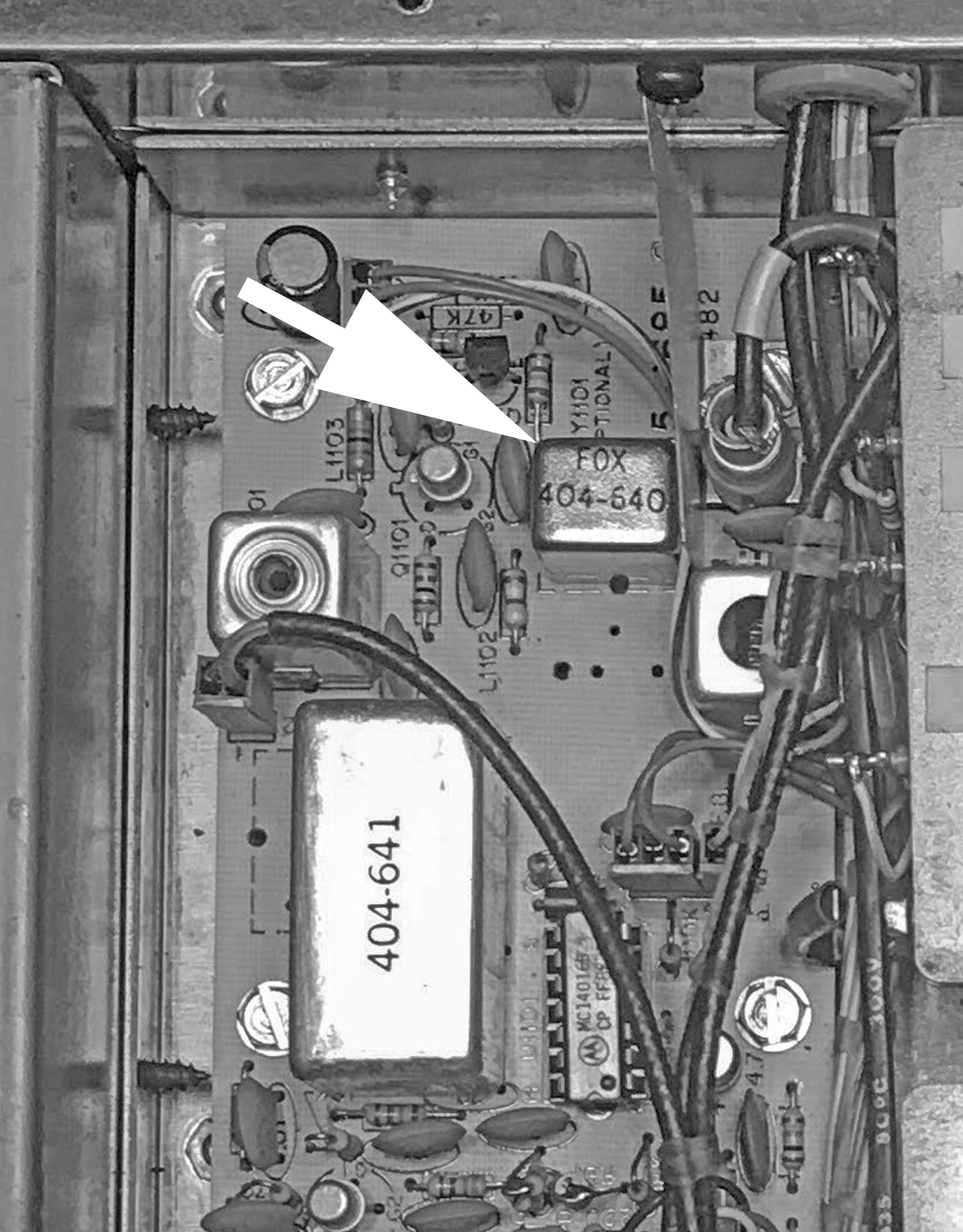
Receiver sensitivity is better than 0.35 µV. Selectivity with the stock filter is 2 kHz at 6 dB down. The stock filter is a six pole 8.83MHz filter, while the optional filter has 4 poles (only used on receive) for a total of 12 poles of IF filtering. Photo shows the location of the optional 4-pole filter.
Unfortunately there was no option for a CW crystal filter. Heath used an active audio filter instead. The CW active audio filter is 250 Hz at 6 dB down centered at 700 Hz.
Overall stability is better than 50 ppm drift from turn-on. Numerous weak “birdies” and other miscellaneous strange noises are down far enough that they should not get in your way. There is no way to shut off the AGC.
Power output is continuously variable. The PA transistors are thermally protected against high SWR and will deliver 90 percent of the rated power with an SWR of less than 2:1.
Early units had significant problems with the CW wave shape and length. Not only was the rise time abrupt, but the transmitter took a full 26 milliseconds to shut off upon key up. This made CW speeds at or above 20 WPM impossible. Heath would supply a fix for this problem to anyone who asked and incorporated a permanent fix into later units. Whether or not the unit you’re looking at has this problem is impossible to say with only casual inspection.
Truly, this was the most complex and exhausting kit Heath ever offered. In the end, Heath realized the HW-5400 was too complicated and too expensive given fierce competition from other ready-made rigs. They pulled it from production and cut their loses saying, in effect, “enough is enough.” Heath lost a lot of money on the 5400 and vowed never to do it again.
The HW-5400 requires a frequency counter and a VOM or VTVM with an RF probe for alignment.
References:
Review. Ham Radio. Feb 1984, p. 96.
Review. QST. Oct 1984, p. 34.
Review. CQ. Dec 1987, p. 18.
Frequency slewing speedup. QST. Sep 1988, p. 43.
Improved RIT and split-freq. QST. Sep 1988, p. 42.
Improved clock setting. Ham Radio. Apr 1989, p. 74.
Battery backup for. QST. Jul 1990, p. 37.
GENERAL
Frequency coverage:
80M - 3.450 to 4.05 MHz
40M - 6.950 to 7.35 MHz
30M - 10.00 to 10.20 MHz (receive only)
20M - 13.95 to 14.40 MHz
17M - 18.018 to 18.218 MHz
15M - 20.95 to 21.50 MHz
12M- 24.84 to 25.04 MHz
10M - 28.00 to 29.75 MHz
Readout accuracy: to the nearest 50 Hz
Frequency control: synthesized
Frequency tuning rate:
slow: 50 Hz per step, 1.25 kHz per knob rotation
fast: 1 kHz per step, 25 kHz per knob rotation
Tuning backlash: none
Split frequency operation: transmit from memory frequency, receive from displayed frequency
Memory: stores one frequency per band (the display frequency is also saved
Stability: less than 50 PPM drift from cold start
Modes: USB, LSB, CW (wide or narrow)
RECEIVER
Sensitivity: less than 0.35 µV for 10 db S+N/N
Selectivity:
standard filter: 2.0 kHz at 6 db, 6 kHz max at 60 db
optional HWA-5400-2 filter: 1.8 kHz minimum at 6 bd
CW active audio filter: 250 Hz minimum at 6 db, centered at 700 Hz
Overall gain: less than 1 µV FOR 0.25 watts audio output
Audio output: 2 watts minimum into 4Ω, less than 10% THD
AGC: selectable fast or slow (no off position), no more than 8 db audio change for a 100 db or greater signal input
IMD: 70 db minimum at 25 kHz
Image rejection: 80 db minimum
IF: 8830 kHz
IF rejection: 100 db minimum
IF shift tuning: ±600 Hz in receive only
Internally generated noise: generally below noise level; all below 1.0 µV
Audio hum and noise: greater than 40 db below maximum output
RIT: ±350 Hz
TRANSMITTER
RF output:
SSB high: 100 watts PEP minimum, except 80 watts at 10 meters
CW: 100 watts minimum, except 80 watts at 10 meters
Duty cycle: continuous SSB (voice); 50% CW, 5 minutes on, 5 minutes off
Load impedance: at least 90% of rated power with less than 2:1 SWR. Protected against high SWR
Carrier suppression: –50 db minimum, reference to 100-watt single-tone 1 kHz
Unwanted sideband suppression: –50 db minimum, reference to 100-watt single-tone 1 kHz
Harmonic radiation: –50 db minimum, reference to 100-watts
Spurious radiation: –60 db minimum, reference to 100-watts
Third order distortion: –30 db minimum, reference to 100-watts PEP two-tone
Transmit-receive operation:
SSB: PTT or VOX
CW: full break-in (simplex only)
CW sidetone: 700 Hz
Microphone input: high impedance (approx. 25kΩ) rated –55 db. Approx. 10 mv
GENERAL
Metering: S-units and ALC
Operating temperature range: 32 to 105 F
Power requirements: 11 to 16 VDC; 120/240 VAC with optional power supply (see HWA-5400-1)
Photos, general information and specifications from "Heathkit: A Guide to the Amateur Radio Products," by Chuck Penson, WA7ZZE. Used with permission.