Note
The SB-634 provides the same basic features and serves the same basic purpose as the SB-630, but is designed to match the SB-104 transceiver.
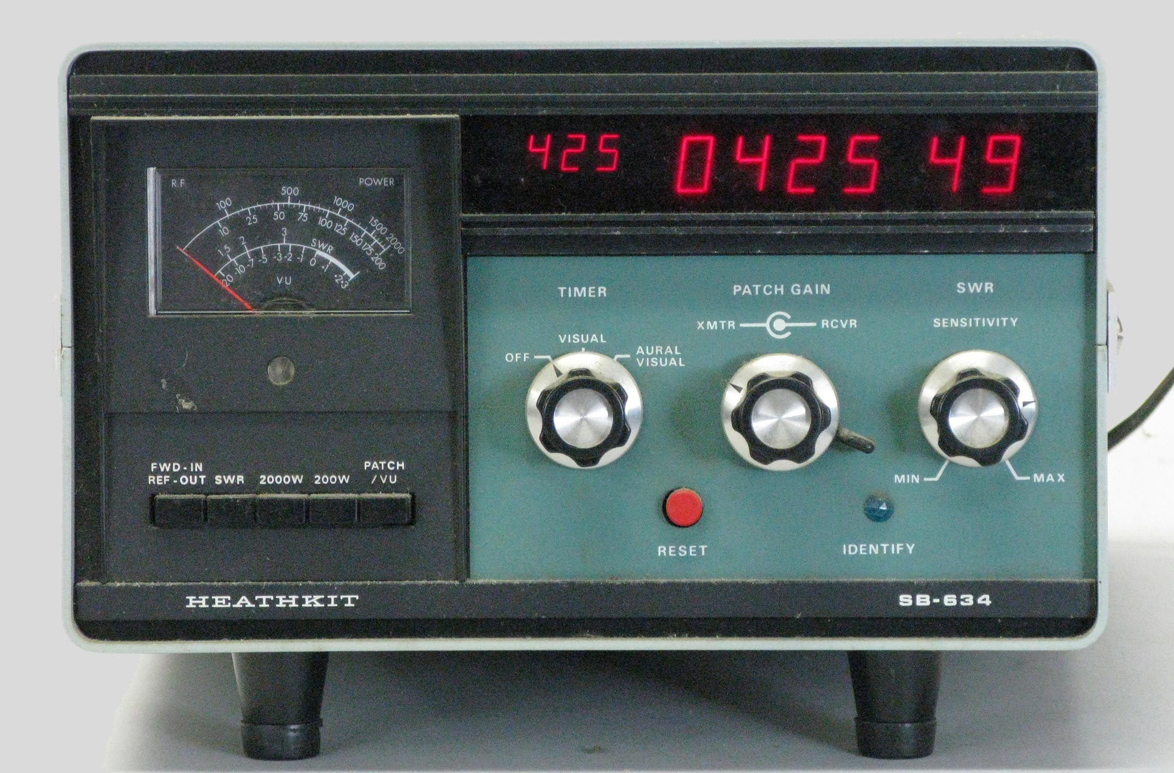
The SB-634 is built on three PC boards and is really just a collection of existing Heath products put into a single box. The 634 contains a six-digit, 24-hour clock based on the GC-1094, a phone patch based on the old but reliable technology of the HD-19, a power/SWR meter based on the HM-102, and a 10-minute digital ID timer. The power meter is a feature not found in the SB-630, which had only an SWR meter. Overall, the SB-634 is a useful accessory and represents a substantial improvement over the SB-630.
The time and timer displays are seven-segment neon tubes of the same type as the GC-1005 digital clock and several other products.
The console has a built-in power supply, but the only features that use it are the clock and the 10-minute timer. The rest of the functions are self powered and can run with the unit unplugged.
When activated, the 10-minute identifier time appears to the left the main time readout and is displayed in three smaller digits. The counter starts at 0:00, counts to 9:59, and resets to zero. Then, depending in the setting of the timer function switch, a light will light, or light will light and an alarm will sound for about one second. The timer can be reset at any point in the cycle by means of a front panel button and can be disabled if desired. When first activated, the timer may indicate a random time and may display some non-numeric characters until reset.
The power/SWR meter has a range of 1.8 to 30 MHz and will read to 2000 watts in two scales or 0-200 and 0-2000 watts. With a simple front panel adjustment, power readings of 1-20 watts may also be made. SWR sensitivity is less than 10 watts. Caution: A load must be connected to the output connector on the power/SWR meter. Insertion loss is negligible.
Front panel controls include a row of push buttons for control of the power/SWR meter and controls for timer function, phone patch transmit and receive gain, and SWR sensitivity.
Rear panel controls include phone patch null adjust, a monitor/null switch, and three switches to set the clock. Rear panel connections include SO-239s for RF connection to the SWR meter, RCA jacks for Hi-Z or 600Ω phone patch output to the transmitter and loop-through receiver audio, and screw terminals for connection to the phone line (polarity is not important). Standard SB two-tone green wrinkle paint.
LOW POWER MEASUREMENTS
The SB-634 can be used to measure power levels from 1 to 20 watts with the following streps.
1) Press the 200W pushbutton.
2) Adjust transmitter output power until the station console meter reads 10 on the 0 to 200 RF POWER scale.
3) Press in the FWD-IN/REF-OUT pushbutton and the SWR pushbutton.
4) Adjust the SWR SENSITIVITY control to obtain a meter reading of 100 on the 0 to 200 scale.
5) Read the power output (0 to 20 watts) on the 0 to 200 scale. For example, a reading of 75 would indicate an output power of approximately 7.5 watts.
TIME / TIMER
Display:
time: 6 full digits (Beckman/Sperry type SP352)
timer: 3 full digits (Beckman/Sperry type SP333)
Time format: 24 hours
Accuracy: synced to 60 Hz power line
Timer interval: 10 minutes with auto reset. Manual reset at any point.
Signal: visual, or visual and aural, switch selected
RF/SWR METER
Frequency range: 1.8 to 30 MHz
Wattmeter accuracy: ±10% of full-scale reading
Power handling capability: 2000 watts maximum
SWR sensitivity: less than 10 watts
Impedance: 50Ω nominal
Connectors: SO-239
PHONE PATCH
Circuit: hybrid; allows VOX or manual operation; single switch control
Telephone line impedance: 600Ω
Null depth: at least 30 db separation between transmit and receive circuits
Receiver impedance: effective match from 3 to 16Ω
Transmitter impedance: 600Ω or high impedance output
GENERAL
Power requirements: 120/240 VAC, 50/60 Hz, 15 watts
Photos, general information and specifications from "Heathkit: A Guide to the Amateur Radio Products," by Chuck Penson, WA7ZZE. Used with permission.