Note
In the spring of 1973 Heath took serious aim at the 2-meter FM crowd and hit the mark with the release of the HW-202 and a group of accessories including a power supply (HWA-202-1), a wattmeter (HM-2021), and an amplifier (HA-202).
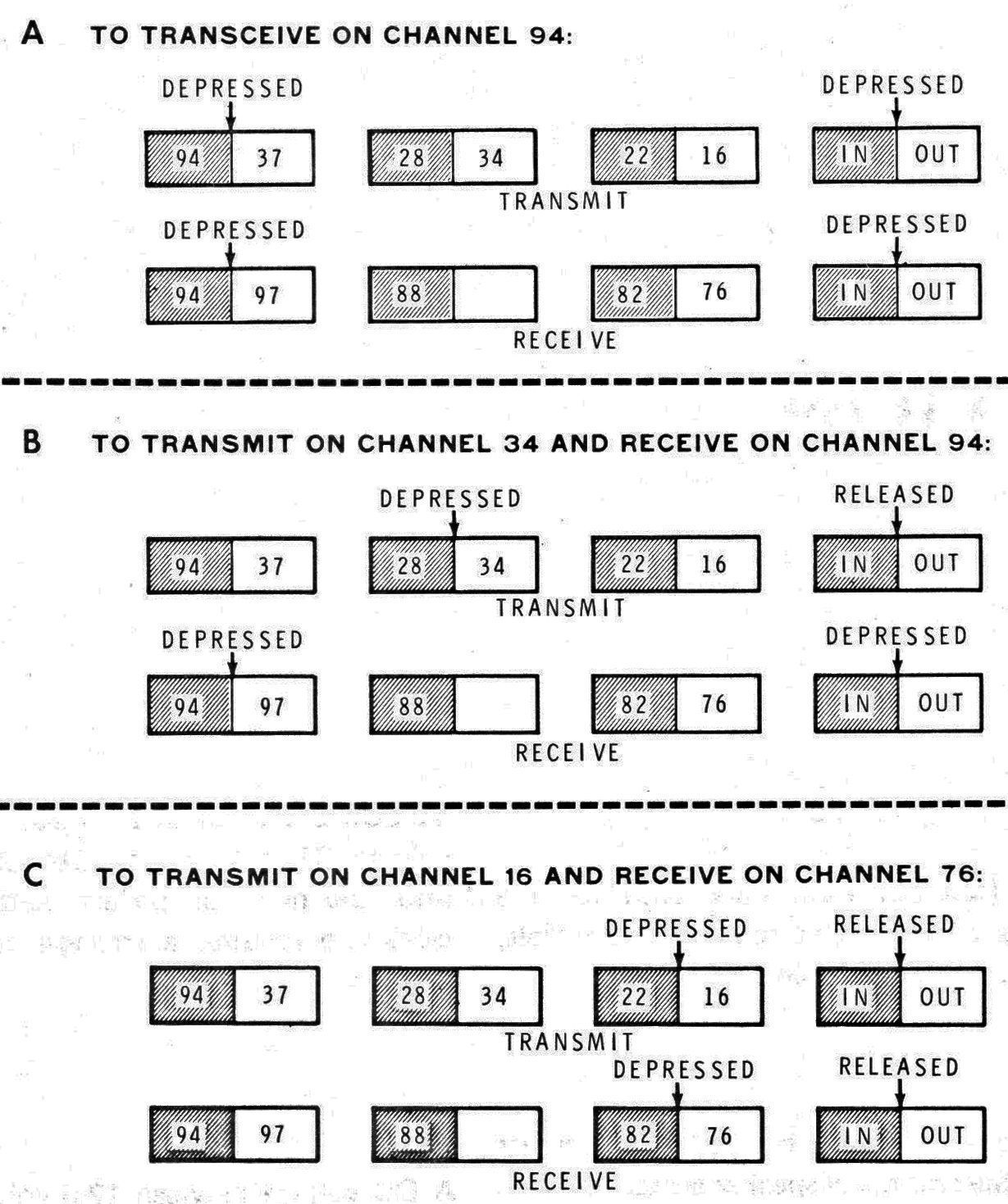
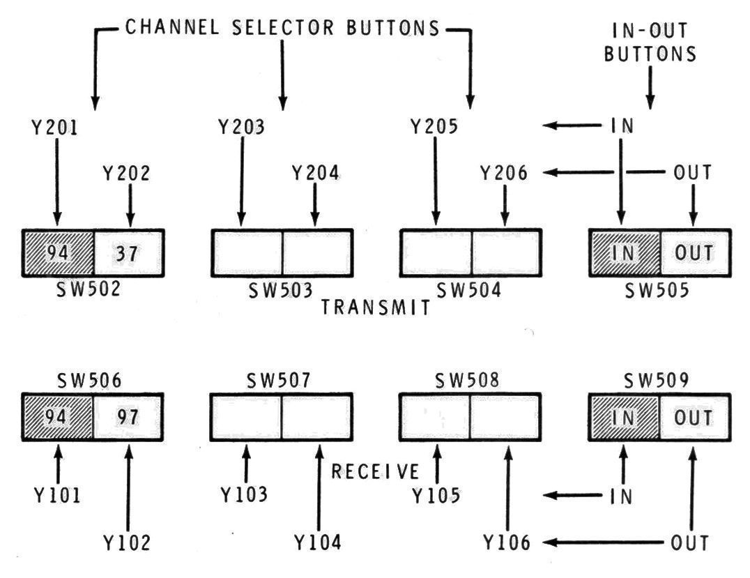
Heath had learned some valuable lessons on VHF and FM with its HW-17, and did everything right with the 202. The HW-202 is a simple, straightforward, crystal-controlled transceiver. It was advertised as a 36 channel radio because it had 6 transmit and 6 receive frequencies that were independently selectable. Of course, in 1973 not many people understood how 2-meters worked and didn’t realize that you probably never would want to transmit, for example, on 146.28 and receive on 146.94. What you really have here is 6 channel radio.
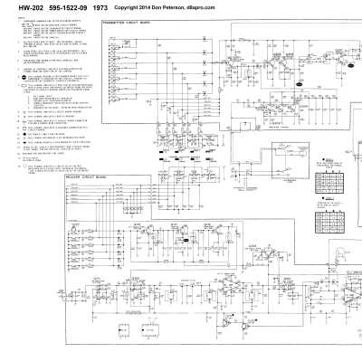
The HW-202 is built on 4 glass-epoxy PC boards and uses a dual conversion receiver with dual-gate MOSFETs in the front end and a 4-pole monolithic 10.7 MHz crystal filter. The receiver sensitivity is better than 0.5 µV with a nominal bandwidth of 22 kHz. The transmitter section provides 10 to 15 watts output and will do so indefinitely without failure into an infinite SWR. Deviation is adjustable from 0 to 7.5 kHz. The HW-202 will cover any 1 MHz segment of the band between 143.9 and 148.3 MHz.
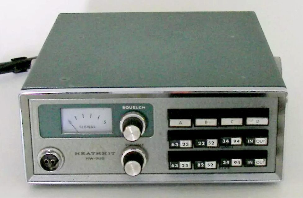
Features include an illuminated meter reading S-units and relative power, a built-in speaker, an optional tone-burst encoder (HWA-202-2), and push button selection of transmit and receive frequencies. Existence of the tone-burst encoder can be determined by the presence of a row of 4 push buttons above the “transmit” frequency push buttons.
Front panel controls include on/off/ volume, squelch, and push buttons for frequency, and (optional) tone burst selection. There is also a front panel mic connector.
Supplied with a Turner 360C ceramic microphone.
Rear panel connections include RCA jacks for a 50Ω antenna and an external speaker. A rear panel switch selects between the internal speaker and an external speaker. There is no rear panel power connector—power input wires come out an opening in the rear panel. The HW-202 must be run directly from a DC source. AC operation requires an external DC power supply. The HW-202 is polarity protected.
CRYSTAL FREQUENCY CALCULATION
The transmitter uses 6 MHz crystals.
Transmit frequency in MHz / 24 = crystal frequency.
Tolerance: 0.0025% or better
Load capacity: 23 pF
Series resistance: 40Ω maximum (–22F to +140F)
Holder: HC-25U
The receiver uses 45 MHz crystals.
(receive frequency in MHz - 10.7) / 3 = crystal frequency.
Tolerance: 0.002% or better
Load capacity: none
Series resistance: 40Ω maximum (–22F to +140F)
Holder: HC-25U
The HW-202 was supplied with crystals for 146.94 simplex and a tilt mounting bracket. The unit can be aligned without instruments—but don’t try it without the book. The two-tone green cabinet has chrome finish around the front panel.
References:
Review. 73 Amateur Radio. May 1974, p. 37.
Review. CQ. Jun 1974, p. 25.
Review. QST. Jul 1974, p. 40.
Adding PL. Ham Radio. Jun 1974, p. 53.
Channel scanning for. Ham Radio. Feb 1975, p. 41.
Modification. CQ. Jul 1975, p. 24.
Protecting transistors. QST. Aug 1975, p. 49.
Antenna plug cautionary note. QST. Sep 1975, p. 45.
Tone pad connections. QST. Jan 1976, p. 43.
Channel scanning for (more). Ham Radio. Mar 1976, p. 68.
Remote control. QST. Oct 1976, p. 40.
RECEIVER
Sensitivity: 20 db of quieting @ 0.5 µV or less
Squelch threshold: 0.3 µV or less
Audio output: 3 watts @ less than 10% THD
Operating frequency stability: 0.0015% or better
Image rejection: –45 db or better
Spurious rejection: –60 db or better
IF rejection: –80 db or better
First IF: 10.7 MHz ±2 kHz
Second IF: 455 kHz
Receiver bandwidth: 22 kHz nominal
De-emphasis: –6 db per octave from 300 Hz to 3000 Hz nominal
TRANSMITTER
Power output: 10 watts minimum
Spurious output: –45 db below carrier
Stability: 0.0015% or better
Oscillator: approximately 6 MHz
Multiplier: x 24
Modulation: phase, adjustable from 0 to 7.5 kHz with instantaneous limiting
Duty cycle: 100%
GENERAL
Speaker impedance: 4Ω
Operating frequency range: 143.9 to 148.3 MHz (will meeting specifications ±1 MHz of alignment frequency within this range)
Operating temperature range: –12F to +122F
Power requirements: 12.6 to 16 VDC at 2.2 amps (while transmitting), 200 mA (while receiving)
Solid State:
diodes: (4) 1N191, (1) MV1638, (14) 1N4149, (1) 1N716A, (1) MZ2360, (1) MZ2362, (1) 1N2071
transistors: (7) 2N5232A, (3) 2N3393, (3) X29A829, (3) 2N3646, (1) 2N3416, (6) 2N2369, (1) 2N3866, (1) MPF105, (3) 2N5294, (3) RCA 40673, (1) 2N5589, (1) 2N5590
integrated circuits: (1) MC1350P, (1) MC1357P
Photos, general information and specifications from "Heathkit: A Guide to the Amateur Radio Products," by Chuck Penson, WA7ZZE. Used with permission.