Note
The earliest references to the SB-10 can be found in some DX-100 manuals, where the unit is referred to as the DX-10. The unit was officially introduced as the SB-10 in August 1958 and was originally designed to be used with the DX-100, but because of significant delays in engineering the DX-10, it was renamed and restyled to match the TX-1 when work on that transmitter began.
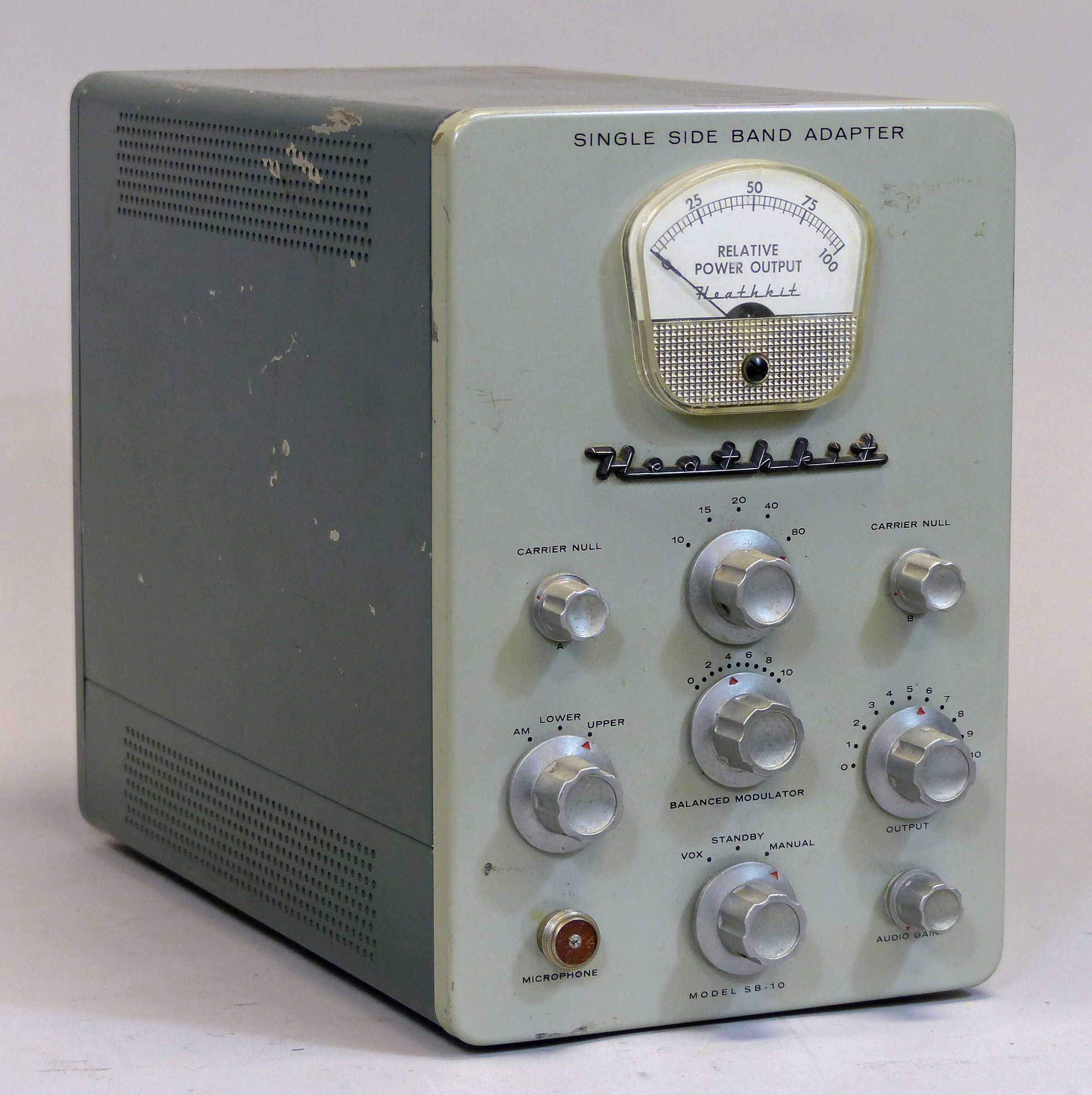
Features include a front panel meter indicating relative power output and is used both in tuning and carrier suppression. There is also a built-in VOX circuit. Front panel controls include carrier null controls, band-switch, mode selector, balanced modulator tuning, RF output tuning, audio gain, and VOX/standby/manual selector. There is also a front panel connector for a high impedance mic.
The SB-10 is a phasing type SSB generator designed to work with the TX-1, but can also be used with the DX-100 and 100B, with some modifications of the transmitter.
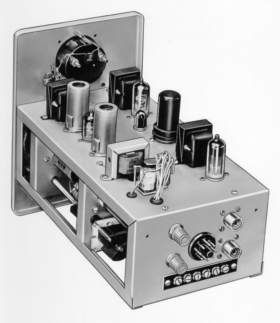
Controls on the rear panel labeled “transmitter sensitivity” and “receiver sensitivity” are for VOX sensitivity and anti-trip. The rear panel also has SO-239 connectors for RF input and output, an octal socket for power input, and screw terminals providing connection for receiver audio, speaker, key, and antenna relay. Refer to Figure 1 for rear panel details.
Since the SB-10 has no internal power supply all voltages must be derived from the transmitter to which it is connected or some other external source. When used with the TX-1 all necessary power may be taken from the transmitter’s accessory socket.
The SB-10 uses nine tubes and is placed in the transmitter’s RF path between the driver and the final amplifier. It requires about three watts of drive, delivers about 10 watts of output, and will provide USB, LSB, or DSB—all with or without carrier. It covers 80-10 meters and is broadband in design so that once tuned for a given band it need not be re-adjusted after normal excursions in frequency within that band.
RF phase shifting is accomplished by a set of precision capacitors in an RC network. A separate set is used for each band. The audio phase shift network is a pre-assembled, sealed plug-in unit (resembling an octal-based metal vacuum tube) made by Barker and Williamson (B&W).
The SB-10’s two-tone green paint scheme matches the TX-1, et al. Early units were supplied with satin finish metal knobs while later versions used polished knobs. The SB-10 was sold for about five years and works pretty well.
References:
Review. QST. Aug 1959, p. 45.
Extra VOX sensitivity. QST. Jul 1959, p. 61.
Audio peak limiting. CQ. Feb 1960, p. 48.
Audio filter for. QST. Aug 1960, p. 48.
Use with Johnson Viking Valiant. QST. Aug 1960, p. 48.
Use with Johnson Viking II. CQ. Feb 1960, p. 30.
Use with Johnson Valiant. QST. Aug 1960, p. 48.
Use with Johnson Viking Ranger. CQ. Mar 1961, p. 67.
Use with Johnson Ranger. CQ. May 1964, p. 41.
Filter modification. CQ. Aug 1961, p. 96.
Distortion. CQ. Oct 1961, p. 83.
Use with TX-1/HA-10/phone patch. CQ. Jul 1962, p. 80.
Make it a complete transmitter. QST. Aug 1962, p. 12.
Use with DX-60. CQ. Jan 1963, p. 74.
Use with DX-40. 73 Amateur Radio. Feb 1963, p. 50.
Use on 6 meters. CQ. Nov 1963, p. 97.
Use with the ARC-2. 73 Amateur Radio. Sep 1964, p. 68.
Various problems to look for. CQ. Oct 1964, p. 80.
Drive problems with TX-1. CQ. Nov 1964, p. 114.
Lots of general information. CQ. Mar 1965, p. 65.
Use on 4467.5 kHz CAP freq. CQ. Jul 1969, p. 86.
Upgrading. CQ. May 1970, p. 22.
Problems (brief). CQ. Apr 1973, p. 16.
Story part 1. Electric Radio. Jul 2011.
Story part 2. Electric Radio. Aug 2011.
Story part 3. Electric Radio. Sep 2011.
Power output: 10 watts PEP
Excitation requirements: less than 3 watts
Output: Pi network coupling to low impedance for coaxial line
Input: low impedance for coaxial line
Band coverage: 80, 40, 20, 15 and 10 meters
Circuit: phasing method of SSB signs generation, with built-in VOX
Unwanted sideband suppression: in excess of 30 db
Carrier suppression: in excess of 40 db
Meter: 200 µA
Power requirements:
350 VDC, 85 mA average, 30 mA standby, 140 mA transmit
6.3 VAC, 3.5 amps
Tubes: (1) 6AL5, (1) 6BQ5, (1) 6CL6, (5) 12AT7, (1) 12AX7 (five tubes on top of chassis, four below)
Photos, general information and specifications from "Heathkit: A Guide to the Amateur Radio Products," by Chuck Penson, WA7ZZE. Used with permission.