Note
The Elecraft K2 occupies a legendary status in amateur radio, serving as the genesis of the Elecraft brand. Its lineage is a story of two designers aiming to revive the DIY spirit of Heathkit while pushing the boundaries of receiver performance.
The K2 was born from a collaboration between Wayne Burdick (N6KR) and Eric Swartz (WA6HHQ).
Design Philosophy: Wayne had a background in QRP kit design (NorCal 40, Sierra), while Eric was a DX and contest enthusiast. They combined these interests to create a "true dual-purpose" rig: a radio that had the high-performance receiver of a home station but was efficient and light enough for a backpack.
The Name: Interestingly, the name was almost a joke. After designing the "Sierra," Wayne wanted to avoid mountain names. They initially suggested "2K" (for the year 2000), but realizing that was the name of a famous high-power amplifier (the Hnery 2K), they reversed it to K2—only to realize they had accidentally named it after the world’s second-highest mountain anyway.
Impact: When released in 1999, it set a new industry standard. The ARRL lab confirmed it had the highest close-in dynamic range of any radio they had ever tested at the time.
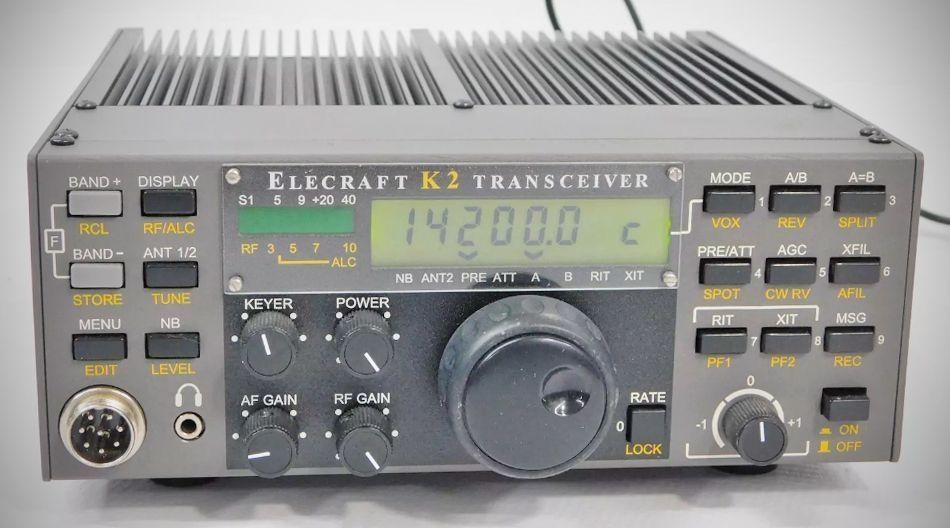
The Elecraft K2 is a high-performance, synthesized CW/SSB transceiver designed for all HF amateur radio bands. It is a "true dual-purpose" rig, offering the features of a home station while remaining compact and lightweight for portable use. The transceiver is built using a modular design that minimizes complex wiring and provides isolation between analog and digital sections.
Includes a digital voltmeter, ammeter, wattmeter, RF probe, and frequency counter for self-alignment and troubleshooting.
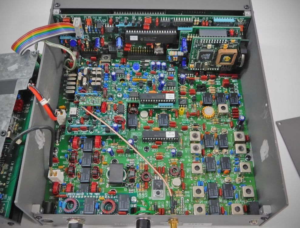
Consists of three main circuit boards (Front Panel, Control Board, and RF Board) with the ability to add internal options easily. Uses latching relays for all switching to minimize current drain during operation.
Offers a wide range of options including an internal 100-watt final stage, SSB adapter, automatic antenna tuner, and noise blanker.
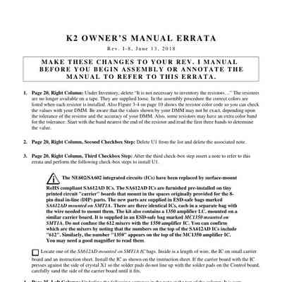
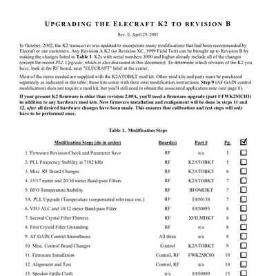
In October, 2002, the K2 transceiver was updated to incorporate many modifications that had been recommended by Elecraft customers. Any Revision A K2 (or Revision XC, 1999 Field Test) can be brought up to Revision B by making the changes listed in the attached PDF. K2s with serial numbers 3000 and higher already include all of the changes (except the PLL upgrade, which is also discussed in the document).
How to Identify a Revision B Model
– Serial Number: Units with serial numbers 3000 and higher are factory-built as Revision B.
– Internal Label: If you open the case, look at the center of the RF board near the "ELECRAFT" label; it will specifically state "REV B."
– Firmware: Holding any switch during power-up will display the firmware version. Revision B units run version 2.04 or later.
NOTE: Updating the K2 to revision B involves a considerable amount of component removal. You will need a full-size, hand-operated vacuum desoldering tool.
The revision B of the Elecraft K2 (introduced around serial number 3000 in October 2002) was a significant production update that consolidated many early user-requested modifications and performance improvements.
Instead of a single change, "Revision B" refers to a new set of PC boards and a collection of hardware and firmware enhancements designed to improve stability, signal purity, and usability.
Key Improvements in Revision B
1. Frequency Stability & PLL Enhancements
PLL Frequency Stability: Improved stability at specific frequencies (notably around 7182 kHz) to prevent the reference oscillator and VCO from interfering with each other.
BFO Temperature Stability: Improvements to the BFO (Beat Frequency Oscillator) circuit to reduce frequency drift as the radio warms up.
VFO ALC Mod: Enhanced Automatic Level Control in the VFO to reduce spurious outputs across different bands.
2. Receiver & Filtering Upgrades
Improved Grounding: Better grounding of the IF crystal filters (X7–X11), which significantly improved the receiver's stop-band attenuation (the ability to block out-of-band signals).
Filter Flatness: Enhancements to the second crystal filter to ensure a flatter frequency response.
Narrower Bandpass Filters: The 15/17m and 20/30m bandpass filters were redesigned to be narrower, providing better image rejection and reduced intermodulation from strong nearby broadcast stations.
3. Audio & Usability Changes
Smooth AF Gain: The audio gain control was rewired from a balanced to an unbalanced configuration. This eliminated the "scratchy" noise often found in early units and allowed the volume to be turned completely off.
Sinewave Sidetone: The sidetone circuit was modified to produce a cleaner sine wave rather than a square wave, making "zero-beating" (matching your frequency to another station) easier on the ears.
Jumper Block Power Switch: The physical voltage selector switch on the control board was replaced with a jumper block. This prevented users from accidentally moving the switch and losing their power supply voltage readings.
4. Firmware & Logic Updates
Firmware Version 2.04: This revision included major firmware updates for the main microcontroller (U6) and the I/O controller (U1).
Expanded Scanning: Increased the number of transverter bands from three to six and added new scanning modes.
60-Meter Support: The revision B boards were updated to accommodate the K60XV option, allowing the transceiver to operate on the 60-meter band.
Specifications
(All measurements are typical and made using a 14.0 V supply and 50-ohm load)
Frequency Range (Basic Kit): 80–10 meters (3.5–4.0, 7.0–7.3, 10.0–10.2, 14.0–14.5, 18.0–18.2, 21.0–21.6, 24.8–25.0, 28.0–28.8 MHz). 160m and 60m are available via options.
Supply Voltage: 9 to 15 VDC with reverse-polarity protection.
Current Drain (Receive): 120–150 mA (minimum config); 180–250 mA typical.
VFO Stability: < 100 Hz total drift typically from a cold start at 25°C.
Memories: 20 (10 band-assigned, 10 general-purpose).
Transmitter
Power Output Range: < 0.5 W to > 10 W (typical).
Current Drain (Transmit): 2.0 A typical at 10 watts.
Spurious Products: –40 dB or better at 10 W (–50 typical).
Harmonic Content: –45 dB or better at 10 W (–55 typical).
Keying Speed: 9–50 WPM (Iambic A and B).
CW Sidetone: 400–800 Hz adjustable in 10 Hz steps.
Receiver
Sensitivity (MDS): –135 dBm (Preamp On); –130 dBm (Preamp Off).
Blocking Dynamic Range: 125 dB (Preamp On); 133 dB (Preamp Off).
Selectivity (CW): 7-pole variable-bandwidth crystal filter (approx. 200–2000 Hz).
Selectivity (SSB): 7-pole fixed-bandwidth crystal filter, 2.2 kHz typical (with optional SSB adapter).
Audio Output: 1 watt maximum into 4-ohm internal speaker; rear-panel jack for external 4–32 ohm speakers/headphones.