Note
QST, Dec 1955, p. 165.
QST, Jul 1956, p. 147. (power supplies for)
Walter Ashe catalog 1957 (probably issued in 1956), p. 9.
QST, Feb 1958, p. 141. (PMR-7A)
Allied Radio catalog 1959 (copyright 1958), p. 381.
Allied Radio catalog 1960 (copyright 1959), p. 394.
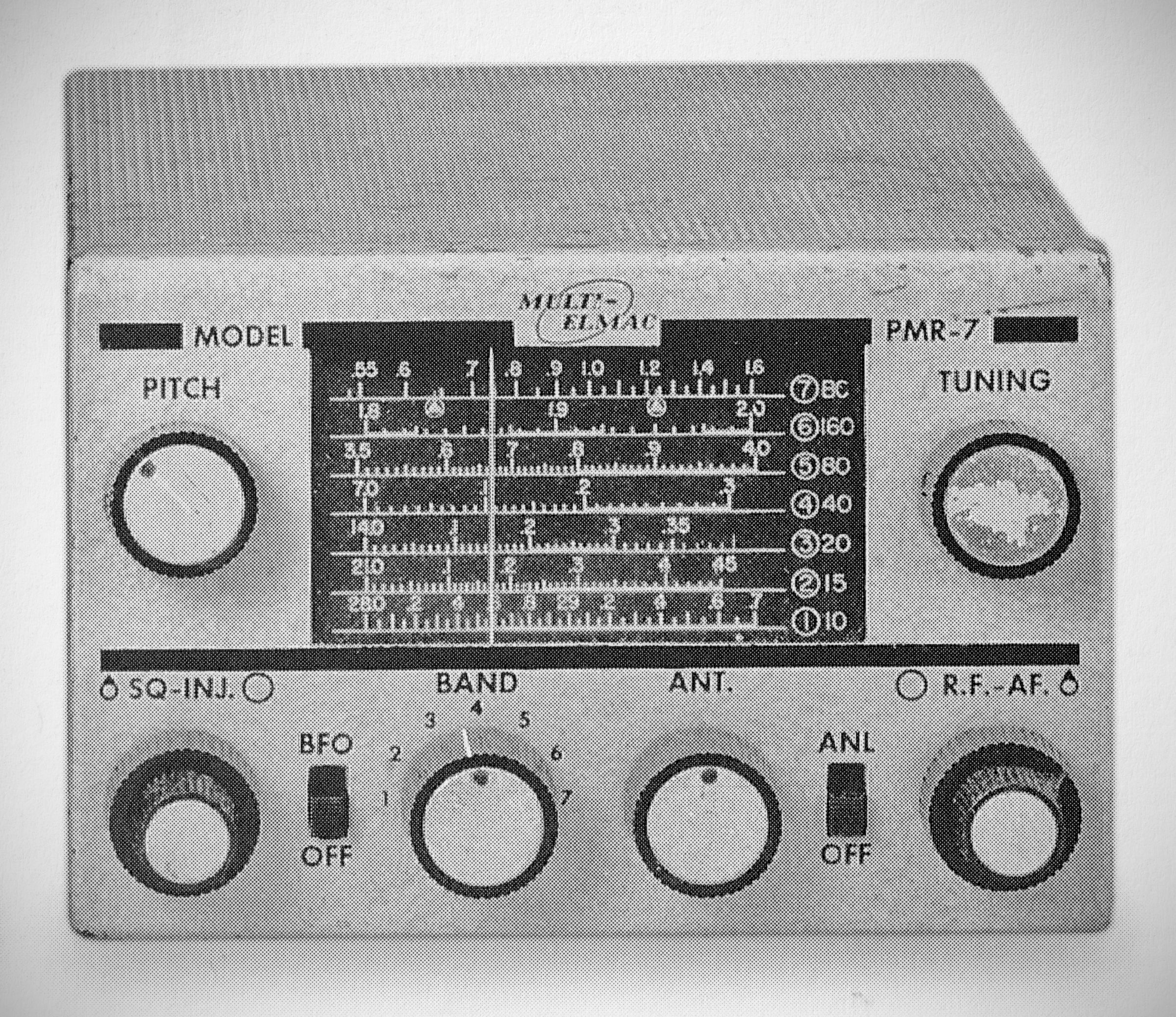
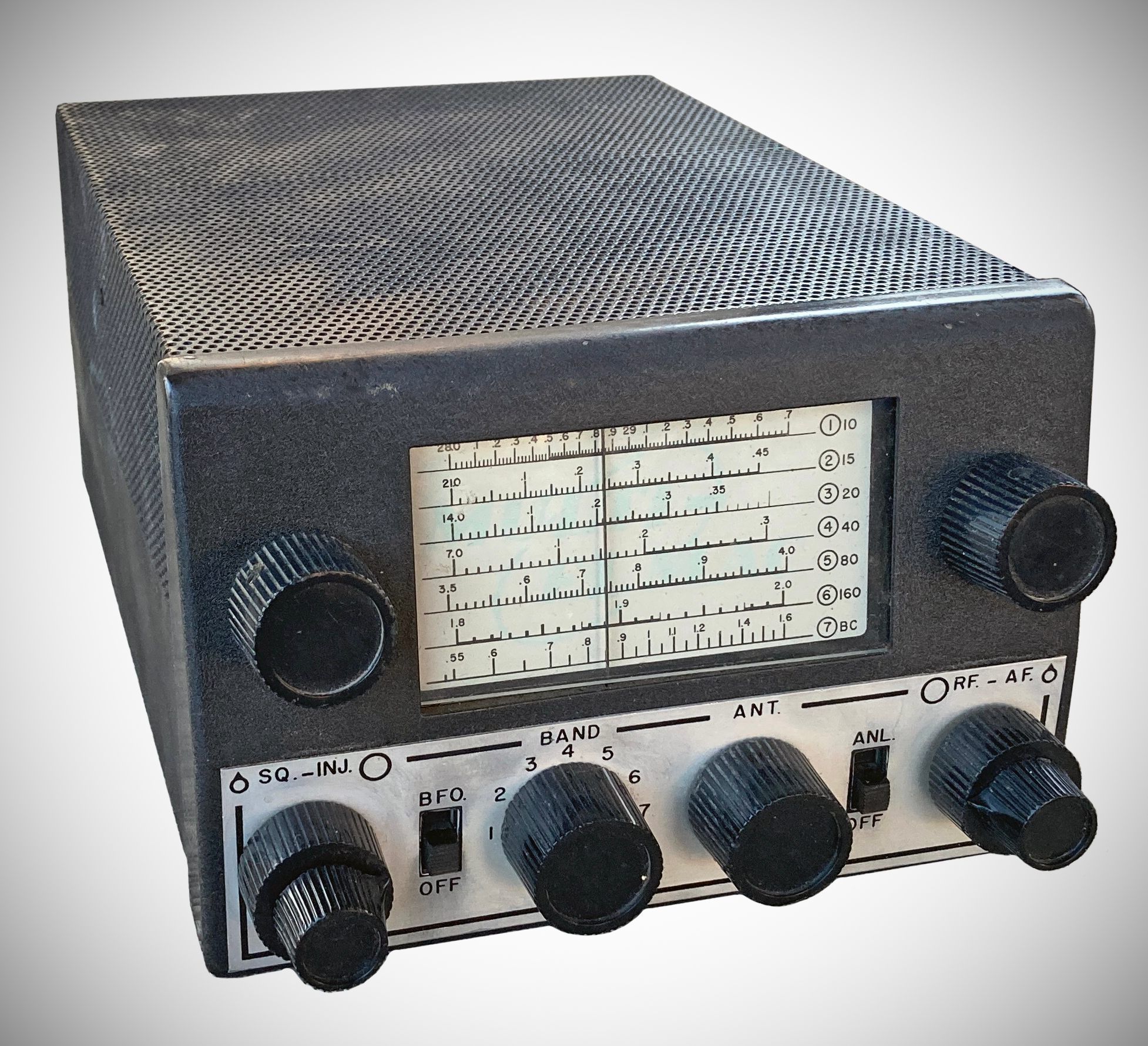
The PMR-7 is a ten tube double conversion superheterodyne covering the 160, 80, 40, 20, 15, and 10 meter amateur bands, plus the standard broadcast band. Designed primarily as an efficient communications receiver for mobile use, it is also especially suitable, because of its small size, for (1) marine and aircraft installations; (2) portable operation; and (3) as a fixed station or monitoring receiver. It is not intended as a converter or accessory to another unit, but a complete receiver, employing a separate power supply and speaker as described in this manual. Every effort has been made to furnish the user with an extremely stable receiver of rugged construction, compact layout, and high sensitivity.
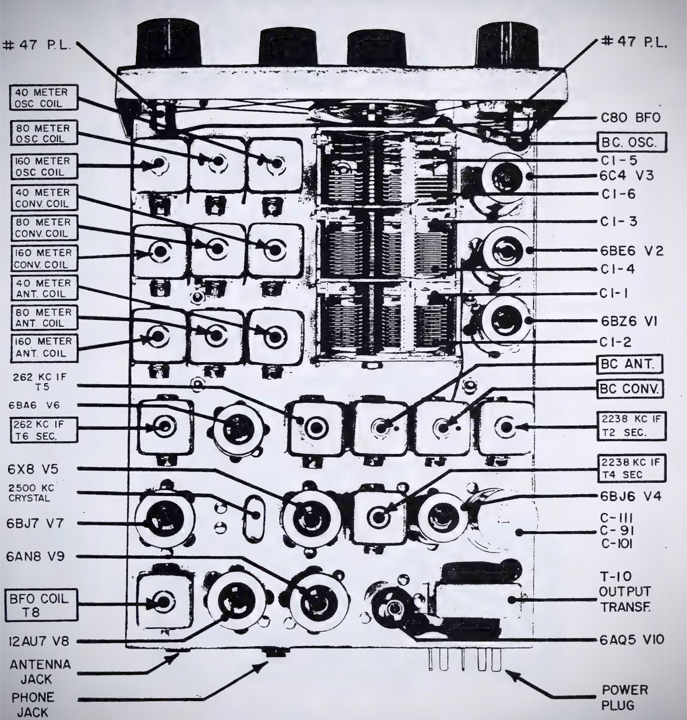
The circuit consists of one stage of radio frequency amplification, a first mixer and stabilized local oscillator. The output frequency of the first mixer is 2238 kHz. and there is one stage of amplification at this frequency. The second mixer and crystal controlled oscillator are combined into a single dual purpose tube. The output frequency of the second mixer is 262 kHz, and there is one stage of amplification at this frequency. The detector, delayed AVC and ANL are combined into a single triple diode tube. The first audio amplifier and squelch control are combined into a dual purpose tube. The audio output is a beam power amplifier supplying sufficient audio output for speaker and headphone operation.
A squelch circuit enables the receiver to be automatically silenced when no signal is being received. The squelch tube functions to cut off the audio amplifier when no AVC voltage is developed. The threshold for the squelch can be controlled from the front panel for varying conditions of noise. If the control is adjusted just above the threshold, that is to just squelch the receiver, an increase in signal of 0.5 microvolt will open the squelch circuit.
Delayed AVC is used in this receiver to provide maximum sensitivity with the use of AVC. In ordinary AVC circuits, inherent noise in the receiver will produce some bias voltage. This bias voltage when applied to the amplifiers will reduce the sensitivity of a receiver. A system employing delayed AVC prevents this bias from being applied to the amplifiers until the input signal is in excess of 8 volts at the AVC rectifier diode.
The BFO in the receiver injects 262 kHz into the output IF amplifier through an isolation amplifier. Both the pitch and the amount of injection are adjustable from the front panel. The purpose of the isolation amplifier is to prevent the BFO from locking in with the signal present at the IF amplifier and to allow variation of the injection voltage without varying the BFO frequency. Variable pitch and injection are a "must" when receiving CW and SSB signals.
The ESS-3 "S" Meter is an optional accessory external 0 - 1 mA meter calibrated in "S" units.
Requires optional PSR-117 AC power supply, or PSR-612 DC power supply.